Dan Roem; lane O. Bear Chapter from the book “Visual Thinking. How to “Sell” Your Ideas Using Visuals »
Publishing house "Mann, Ivanov and Ferber"
Who are our clients?
Consumer crisis
So, everyone in the company agreed that we don't know our customers well enough, so to determine what kind of customer we need to find and target with them, the first step is to create a profile of them and understand who they are. Let's pick a large company and use what we know about it to create a profile of our customer base. We know that our base will include many various information, and we want to look at it from different angles, so that we can then tell people about it both in our company and outside it. Therefore, we will draw.
So, we already know how to choose the right structure - for this we will use the Code of Visual Thinking, and since in this case our problem concerns people (“who” our clients are), the Code recommends starting with a portrait, or with a qualitative representation.
You remember that the first way of perception was to see “who” or “what.” This means that we saw and recognized objects due to the presence of distinctive visual features: a certain set of components, shape, proportions, color, texture, etc. To show what we saw to other people, we create a portrait (or qualitative representation) that reflects the most important of these properties, focusing on those that make our object more recognizable and individual. Whatever we want to show our audience - a ball, a bird, a house or a smile - it is portraits that allow us to present the distinctive characteristics of objects through which we recognize them. These serve as the basic "building blocks" for all the other drawings we'll create. Portraits do not reflect the number of objects, their location in space and time and the relationship between them - there are other structures for this - but they are an excellent Starting point, because they help us immediately understand and track who is who and what is what.

Portraits: general rules of construction
- Keep it simple. Remember: your goal is not to achieve Rembrandt's level of skill - in fact, an overly detailed and elaborate drawing inevitably attracts too much of the audience's attention and distracts from the message you intend to convey to them. The simpler the better: try to visually “telegraph” the idea rather than paint a picture.
- Decorate your lists with miniature drawings. The purpose of portraiture in business is to stimulate unexpected quantitative ideas that arise when hand and imagination work in unison; a visual reflection of someone or something (regardless of the actual similarity and details) always gives rise to new ideas that may never arise when compiling an ordinary list.
- Describe visually. If you're short on time (and time is always short in business), remember that drawings will always be more effective if you compare things rather than describe them. Comparative portraits can be simple sketchy smiley faces, but even such minimal visualization brings the objects to life and makes them more memorable.

Having remembered these rules, let's return to creating a portrait of our client. We have already chosen the structure, and now we will answer five questions of the SQVID model. So, what should the drawing be like - simple or drawn in detail? Considering that this is our first attempt to graphically represent our client, it is better to go with something simpler. Quantitative or qualitative? Since this is a portrait, the default picture will describe the quality.
Vision or execution? At this stage, we are not yet discussing where we would like to go, nor how to do it, so this question does not apply to our drawing: we will simply skip it. Individual characteristics or comparison? Since we'll be looking at the full range of clients, it's best to choose a comparison. Change or normal state, i.e. status quo? Given that we ultimately hope to identify a customer base, at this stage our portrait should reflect the status quo situation, but depending on what we discover, we may need to depict changes later. Summarizing all of the above, we come to the conclusion that the initial structure of our portrait will be quite simple: a laconic portrait of several types of clients, something like ©©©. So, we are finally ready to start drawing.

Where do we start? Before you think seriously about the answer to this question, remember that the first sketch on a napkin is always the most difficult and also one of the least important. We will introduce other elements into it, we will change it, and perhaps we will simply erase it initial version. It is immeasurably more important to draw something at all on a sheet of paper, rather than sit over it and worry about what it should be. Good way to start drawing - draw a circle and give it a name. Since we've determined at this point that we don't know our client as well as we should, let's start with what we do know: ourselves.
This portrait should help us differentiate the object from others, so I suggest adding some kind of visual symbol to the first circle that will make “us” more recognizable.

Does presenting ourselves this way allow us to find any ideas about how we could present our main client? What if we finish drawing it too?
Even such a drawing with a minimum number of components gives some idea of the relationship between us and the client and helps us imagine how to approach the creation of his portrait.
If we're going to show people, why not start with ourselves again? This won't tell us anything about our clients, but by drawing ourselves (something we know very well), we will have a framework to think about how to portray them.

So, this is us: emoticons, which we have already mentioned more than once, begin to appear in the picture.
Feeling empowered by portraying ourselves, we are finally ready to begin creating portraits of our clients.
So, here they are - our clients. Interestingly, the number of their types is greater than we initially thought; you see: we have just started creating a portrait, and we have already begun to think differently about our clients. We spent four to five minutes on this picture and already created a basic portrait that clearly indicates who is who in our business; By visualizing the situation, we initiated a lot of new ideas and, in addition, painted a picture that others would understand at first glance.
Now, before we begin demonstrating our creation, we only have one thing left to do - provide all the elements with explanatory captions.
We instinctively assigned names to all the components of the drawing as we created it - in fact, one of our first tasks was to somehow name our first circle. Subsequently, when adding emoticons, we continued to mark them somehow and did the right thing. The fact is that while our visual centers do not need anything other than graphic images, information processing areas in our brain require names and titles. If objects do not have a suitable name, a person, as a rule, begins to assign their own names to them.
In addition, as you remember, we must name the entire drawing. Of course, we ourselves know very well what we wanted to portray, but we should not forget that other people may look at our creation from a different point of view, perhaps completely missing the main idea that we wanted to convey to them. Hence, always give titles to your pictures; The title should usually be placed at the top.

Although our picture is extremely simple, it is a very useful “framework” for reflecting other quality characteristics of our clients. For example, recent market research showed that each of the types of customers we identified expected specific features and functions from our accounting software. Because our client executives are ultimately responsible for everything (both good and bad) that results from their employees' use of our software, they want software that is accessible to their staff but not accessible to other users; in other words, they strive for safety above all else. Sales personnel want a product that can make their task easier - selling their company's services; therefore they need software with a good reputation, the main thing for them is a popular brand. Accountants, of course, value accuracy and consistency above all else and strive for the reliability of the programs they use. And engineers always want to have programs that can be easily combined with other systems and can be easily upgraded, that is, their main requirement is software flexibility. As you can see, the wish list is quite large, and it is much easier to digest it, again resorting to visualization. Let's draw another picture.

So, we have two portraits of clients: one depicts themselves, and the second represents their wishes. But these are just two of the many versions we could create at this point. In different companies and in different contexts, these “portraits” may be called plans, diagrams, vertical projections, etc., but, in essence, they are all the same and represent a visual report of how something or someone looks - those the “who” and “what” that we see.
How many of our products are bought?
The consumer crisis - this time in numbers
So we saw our customers (at least as we imagine them), noted some of the differences between them, and even began to think about what exactly they expect from the software our company develops. All this is very helpful information, designed to help the company achieve renewed sales growth, but it's just the beginning. To make all this data even more meaningful to us, we need to find out how many customers we have in each category, quantify how many of them are willing to spend money on products like ours, and even try to quantify their attitude towards the products we offer. That is, now we are no longer talking about the categories of “Who” and “What” - now we have to answer the question “how much?” In this situation, the Visual Thinking Code recommends moving from portraiture to diagrams: drawings that reflect quantity, illustrate criteria to be assessed, and present quantitative comparisons. Unlike portraits, which we can create without any quantitative information, diagrams require numbers, readings, and data.

After we notice and recognize someone or something, we note the number of different objects and their components. If "how much" is a small number, our brain quickly calculates the total; Regarding more impressive indicators, we make a rough estimate, and about impressive numbers we simply say: “That’s a lot.” To present this kind of data to other people, we use a diagram (or quantity representation) to transform abstract numbers into a visual, concrete picture of quantity.
Diagrams: general rules
- The most important thing is the data, and it needs to be demonstrated. Many people find studying numbers to be a terribly boring task, so we often try to make diagrams using a variety of, albeit not very necessary, but attractive decorations. We sincerely hope that this will make our pictures more interesting, especially if we intend to show the audience not one, but several such drawings. In this regard, I bring to your attention three valuable thoughts: firstly, necessary, useful information are never boring. If our idea really interests the audience (either because it exactly matches their expectations, or because people are excited about new ideas), you can rest assured that no one will fall asleep during your speech. Secondly, in order to demonstrate an idea and convince people of something, you need to use the minimum possible number of pictures. You should always either limit the number of drawings on the same topic, or combine them into one or two graphs with variable parameters (we'll talk more about this a little later). And thirdly, adding images of stick figures to such presentations - if logical and justified - will greatly enhance their cognitive impact. In other words, if you count customers, show it in your drawing.


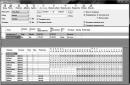
But let's return to SAX. In the process of creating a portrait of our clients, we collected data from the “Who” category. Now we need numbers. After reviewing our company's sales reports, we found that we fortunately had the basic information we needed. In the questionnaire that all our clients fill out during registration, there is a “Position” item, so we can easily determine how many clients of each type we have today. If we wanted to create a graphic that depicted both customers and their number, we might end up with something like this.
If we talk about the quantitative composition of the consumer audience, then it is impossible to come up with anything more accurate than this drawing: in it, it’s as if they gathered in the parking lot near our office and took a group photo. But to be honest, our picture is not good enough: firstly, although we can distinguish representatives of different types in this whole mosaic, we cannot see groups (because they are all mixed together); and secondly, the different categories are very difficult to count and compare. We see their number, but exact mathematical calculations in this case are impossible. Therefore, it is necessary to include the coordinate system and summary data in the figure.

Well, that's much better. We can now categorize and compare different types of customers in seconds. Let us immediately note that among our clients there are much more accountants than sellers; There are almost two times fewer engineers than sales specialists, and there are very few managers. However, it should be recognized that creating such a drawing can take a lot of time. We need a simpler way to show quantitative metrics so that we don't have to depict each customer individually. Let's try this: let's give up the drawing altogether and just show the numbers on a piece of paper.
In this case, we also receive an accurate quantitative expression of the data, but we lose the immediate perception that a visual presentation provides. Now we take a few seconds to scan the rows and columns of the table and compare information about different types of consumers. In addition, in this table, as they say, there is nothing for visual memory to cling to: if we, for example, are not distinguished by the ability to remember exact numbers, then in this situation we will not be able to resort to the help of a broader context. In other words, it is clear that we need a combination that combines the best features of both of these options for presenting quantitative data. Maybe a bar chart would be optimal?


This is exactly what we need: it is clearly visible who we are talking about and how many people are in each category. In addition, exact numbers are indicated. In other words, we have precognitive “quantitative columns” that our eyes can “read” almost instantly, immediately compare and recall some time later, after we have forgotten the numbers. “I don’t remember exactly who and how many, but I know that there are many more accountants among our clients than salespeople.” Just perfect: This is where a simple bar chart really works best.
But seeing exactly how many of each type of customer you have is only one part of the equation. In fact, our task is to find out what the share of managers, accountants and sales agents in the total number of sales of our products. Only then will we be able to determine which of these categories is the most important for us in order to take the obtained data into account when allocating our fixed and limited marketing budget. If we are only getting a certain portion of the total marketing dollars, we need to know exactly which category should get the biggest piece of the pie. That is why, when we need to see the percentage shares of individual “pieces” relative to the whole, we use a pie chart.

There are no more general numbers here; Instead, we see the share of each type of our clients relative to other categories. Assuming that all customers buy our software equally actively, then when allocating the marketing budget we will need to allocate them an appropriate percentage of the total funds. This will help to divide the money among all types of clients in the right proportions.
However, one problem that is common with charts is that because they only show quantities, it is easy to forget about other important differences that may exist between the objects being evaluated and the objects being compared. In other words, although the numbers presented in a quantitative comparison are accurate, they can still lead us to the wrong conclusion. For example, if the pie chart shown above were the only measure of the number of our clients, then theoretically we would have only one choice - to assume that we should allocate 75% of the marketing budget to accountant clients, since they make up 75% of all registered users our programs. However, it is quite possible that this would not correspond to the real state of affairs in the sales sphere of our company.
Great Battle pie chart
 |
Pie charts highlight another complication: they are at the heart of warfare. |
 |
Between experts in the field information support There is a long war going on as they argue relentlessly about the effectiveness of pie charts as tools for presenting data. On one side of the barricade there are people who consider these diagrams to be a very convenient tool, arguing first of all that they are easy to compile (with the appropriate software): they look attractive and are easy to read. Others object to them, citing the fact that human eyes are worse at noticing proportional differences in the size of sectors than in the length of horizontal or height of vertical columns (which is absolutely true). Based on this, they conclude that pie charts should not be used at all. |
 |
There has been a long-running war among data science professionals as they relentlessly debate the effectiveness of pie charts as tools for presenting data. On one side of the barricade there are people who consider these diagrams to be a very convenient tool, arguing first of all that they are easy to compile (with the appropriate software): they look attractive and are easy to read. Others object to them, citing the fact that human eyes are worse at noticing proportional differences in the size of sectors than in the length of horizontal or height of vertical columns (which is absolutely true). Based on this, they conclude that pie charts should not be used at all. But if the difference between sectors (or stacks) is fundamentally important, and is practically invisible in the figure, it is better to return to another data representation, for example, to a table. |
Let us now imagine that in the process of analyzing the company's sales information, we come to the study of our customers' purchase orders. They indicate the amounts they paid, indicating the names of the customers - not those to whom the software purchased from us is registered, but its direct buyers. Using a different type of chart (not a pie chart, because in this case we are interested in absolute figures, not percentages), we see that over the past year, accountant consumers spent $100 thousand on our products, while sales staff only spent 5 thousand dollars
We see that the picture has completely changed. Although accountants make up a third of the company's registered clients, they purchased slightly more of our products than professionals. And this despite the fact that the group of technical specialists is very small, only the group of managers is smaller than it! This is already interesting - who would have thought that engineers are so actively buying accounting programs! To get an even clearer picture, let's create another chart, this time taking into account the number of customers of each type and the amount they spend on our products. As a result of fairly simple mathematical calculations (we divide the total costs by the number of clients of each category), we get the following picture: one manager spends on average $5,500 on our programs, one engineer spends $5,300, and one accountant only $640.

Wow! Just look: Although IT professionals and executives account for only half of our total product purchases, the individual purchasing power of each of these two categories is almost nine times greater than that of accountants. But all the previous diagrams did not reflect this most important fact. While this chart doesn't show why the value varies so widely across different customer types, it's certainly something to think about. Could it be that technicians are purchasing a significant portion of software on behalf of accountants? If so, they have truly enormous purchasing power. How do you like the fact that only four members of the company's senior management are buying even more of our products? This gives us fundamentally new insights into our customers' purchasing decision-making process. This data makes it clear that we need to pay more attention to the purchasing process of our customer groups such as IT professionals and C-suite executives.
All this should certainly give at least some idea of the sources of our sales problems. It is this question that we will consider next - the “where” structure. But first, let's recap what we learned in this chapter. The graphics shown here include quantitative comparisons, pie charts, and bar charts, just to name a few of the many options. graphical representation"How many". As with the previous structure, portrait, diagramming in different companies and solving different problems will also require different types of this structure. However, as in the case of portraits, these will only be variations of the same theme, i.e. different ways, allowing us to show how many of someone or something are depicted using the first structure we considered.

Where is our core business?
Moving around the map
So, the numbers we just analyzed tell us that CEOs and IT professionals are the categories of our customer audience that account for a disproportionate share of our product purchases. This is an interesting and rather unexpected fact, since we have always assumed that the largest number of our programs are purchased by accountants, because they are the main users. That's why it was surprising; we even doubted that we understood the hierarchy of the client company that interested us. Apparently, engineers there have much more purchasing power than we thought. This got us thinking about the organizational structure of this firm: who manages whom and who reports to whom.
Therefore, now we are faced with a problem from the “Where” category, but not from the point of view of location. We are not interested in what part of the city or in what city the office of a particular manager or accountant is located. This is more of a structural problem: we want to know where, at what point in the decision tree, technical specialists are located, which, as it turns out, are a very important category of our client audience - compared to accountants, sales personnel and company management. Therefore, we need a map of the firm's business structure - and although it is, of course, not actually a geographical map, we will create it as if it were one.

After we have noticed how many different objects and their components there are, we see how they are located relative to each other. We note their positions, relative orientations, and the distances separating them. To present this kind of information to other people, we use maps. This kind of picture reflects the placement of objects, their proximity or distance, overlap, distance and direction. And all this applies not only to geography; thanks to maps, spatial relationships not only between physical objects, but also between any ideas are surprisingly clearly revealed.
Because of their versatility and variability, maps are the most flexible of the six structures; this means that the cards different types may be completely different from each other. However, in reality this is not the case at all; in fact, they are almost all the same, especially in terms of the spatial relationships they illustrate. Starting with a graphic representation of the most salient feature of our "landscape" - be it a mountain, a person or an idea - and with a clearly defined set of coordinates, then add more and more properties and details, include additional layers of relevant information, indicate boundaries and distances, and illustrate relationships and sets common features will not be difficult.

In addition, maps are also the most familiar of the six structures discussed. With so many different types - from organizational charts (which every employee knows how to draw these days) to good old treasure hunting maps (which everyone loves to look at), maps are the most used visual image of all.
Cards: general rules
- Everything has its own geography. Maps are used not only to depict natural landscapes; anything that has many unique components—cities and rivers, or concepts and ideas—can be depicted as a map. The task of the visual thinker in this case is to ask himself: “If these ideas (concepts, elements, components, etc.) were states, where would their borders be and what roads would connect them?”
- North is a state of mind. We are used to thinking of maps as a north-south, east-west coordinate system on which different areas and objects are plotted, taking into account their position in space. But we can map almost anything based on other pairs of opposing concepts: good-bad versus expensive-cheap; high-low vs. winner-loser, etc. Essentially, the only difficulty in drawing most maps is determining the correct coordinate system. Once this is done, putting landmarks on the map is no longer difficult.
- Go beyond the hierarchy. Traditional (hierarchical) "organization charts" are excellent tools for graphically depicting the formal chains of command in an organization, clearly showing who is responsible for what. But if you want to figure out where the less obvious - but usually more powerful - political connections are, it's better to use a tool like a circle "influence map", that is, a diagram depicted by circles and arrows. Collecting the data to build it is much more difficult, but the effort will pay off handsomely if it is necessary to understand what is actually happening within the organization.

But let's return to SAX. From the Visual Thinking Code we know that solving the "where" problem requires a structure such as a map, and from the SQVID model we determine that our drawing should be simple, quantitative, based on vision and individual characteristics, and reflective of the status quo situation. Therefore, we need to draw something between a conceptual model and a treasure map, something that clearly reflects the structure of the company we are interested in. We also know that when creating a map, you should start by drawing the most noticeable characteristic of the “landscape”, which in this case is a very large accounting department - the foundation and basis of the client company’s activities.

And while we've pictured the location where all of the company's accountants work, we also know that our new target customers are not located here, so let's expand the picture to include other parts of the firm.


We also know that all of these groups are managed as fiefdoms, so it makes sense to add boundaries to our map so that we can see who is connected to whom and who has no common ground with other divisions and functions of the organization.

In the real world, bordering states are connected by roads; the same can be said about our client. Let's ask one of our sales representatives - one who is intimately familiar with the reality of the client company - to help us map such paths between different functions and divisions.

Strange! There are absolutely no “roads” between the sales department and the accounting department. The lack of direct connections between them means that these business components have very little influence on each other, and therefore are unlikely to significantly influence each other's purchasing decisions. In essence, our map is ready. Now let's determine where exactly the position of the “treasure” is indicated on it.

So, now we have a clearer and more complete understanding of the structure of the divisions and functions of the client company. We have a very useful big picture, but looking at it, we realize that we certainly need to track the hierarchical relationships between the “domains”: who makes what decisions and who influences whom. Apparently, we need to make another map based on the same “geographic landscape”, only this time we should focus on the real power of any organization - the people. We will approach this question using the same principles, that is, starting with the most visible component of the “landscape”, in this case Marge, the chief executive officer of the company we are studying.

We have to map all the other employees relative to Marge, which means we need a coordinate system relative to her. Only then will we know where to place the next most important elements of the organizational structure - Mary (manages the sales department) and Mildred (manages operations).

Moving on, let's look at middle management: Morgan, Tom, Dick and Beth. These are very important heads of functional departments of the company. And after that, after some thought, we erase the coordinate lines - they only complicate the picture.

Now we're mapping front-line employees. Here’s what’s surprising: we’ve already depicted almost the entire company, but we haven’t gotten to the IT specialists yet (and that’s half of our customers).

One more level, and they finally appear - at the very bottom of the “pyramid”, farthest removed from Marge and the other leaders of the company. Moreover, there are no visible connections with the sales staff. In any case, the map is ready: add a title and we are already looking at the organizational chart of the client company, displaying the location of each of the main groups of our clients on the hierarchical ladder relative to each other.

Organizational charts of this type are the best example of a company map. It is enough to create one such map to understand how easy it is to clearly depict the spatial relationships between many objects. Additionally, org charts are the kind of maps that literally anyone who works at a company will be familiar with (including, most notably, people who complain about their lack of artistic ability), and everyone can draw them. In fact, when we are asked to describe how our organization works, the first (and often only) picture that comes to mind is the traditional hierarchical organizational chart.
We have all worked with organizational charts, we all understand them, and - regardless of whether we are satisfied with our position in it - we like to see ourselves and the people we know represented in the form of such an unambiguous, absolutely understandable and clear structure. Organizational charts give us a sense of confidence in the stability of the world order; We have high hopes for them, confident that they accurately reflect how people in our organization influence each other. This belief, while well-founded enough for organizational charts to remain a favorite way of representing business throughout time, can lead us in the wrong direction. In fact, often the most important thing in an org chart is what it doesn't show... and to see that, you need to look at things differently.
That's what I mean. If we look again closely at the organizational chart we created, we notice an anomaly in it: according to our information, the main buyers of our products are the company's senior executives and technical specialists, and it is these groups that are separated from each other by the greatest distance in the organization. Moreover, as we remember, our first map of the business structure did not reveal any direct “roads” that could connect them.

All this suggests that within the same client company there are two completely different target groups, requiring a fundamentally different marketing approach. Obviously, in this situation it would be correct to try to find out what kind of relationship connects both groups. Then, perhaps, we can develop a single and, therefore, less expensive marketing program that will be effective when working with both main categories of buyers. It is clear that this is a very difficult task, however, if we manage to find common ground between managers and technicians, such efforts will undoubtedly be worth it.

And then we stalled. We couldn't answer that question until one of our sales reps, who was very close to the company, told us about Jason, the technical support prodigy. This young man, who graduated from college only two years ago (the client company was his first place of work), turned out to be a real genius in repairing and setting up laptops. There are legends about him in the company, and as soon as someone has problems with their computer, an employee immediately turns to him. Jason often helped Mildred's head of operations solve problems and eventually became her advisor on any technical issues. So he is the bridge between management and technical specialists. It's definitely Jason. It turns out that when making any computer-related decisions, the employee at the bottom of the hierarchical ladder has the strongest influence on any member of the organization.

Here are the weak and strengths traditional organizational charts: since they represent a “formal” structure, they do not reflect such an aspect as the informal relationships between people - in fact, they determine everything that happens in any organization. But at the same time, any correctly drawn up organizational chart serves as an excellent “skeleton” for drawing real spheres of influence.
Size is one of those visual cues that our mind understands instantly, without any hesitation. Therefore, if we want to add additional layers to the organizational chart we created, we need to use this attribute, then our drawing will clearly indicate how much influence Jason has in his company.

So we found the missing link - Jason. Since all the decision makers in the organization listen to his opinion, he undoubtedly has a very strong influence on acquisition decisions computer equipment and programs. Regardless of whether he is involved in purchasing equipment himself or someone else is doing it, it is obvious that his opinion on this issue is taken into account by everyone: including engineers and accountants, i.e. groups that account for the lion's share of overall purchases, and company executives who make most of the purchases individually. Therefore, it will be very useful to find out what motivates Jason when expressing his opinion (bad or good) about a particular computer program.

Then remember that accountants strive for reliability, and this software quality has some overlap with security.

To begin with, let’s return to the portrait we created earlier, reflecting what each specific category of clients within our client company seeks to achieve when choosing software, but this time we’ll try to indicate the relationships between them - perhaps this way we’ll understand what exactly motivates their Jason's choice. Let's start at the top of the hierarchical ladder and remember that company management values security above all else in computer programs.
And Jason, who communicates freely and constantly with all levels of the organization, understands that the best computer programs must not only meet his basic requirements (compatibility with other systems and ease of upgrading), but also have qualities that are important to company managers and accountants. And he is well aware of their needs, because he is the one who has to listen to all the complaints in the event of a computer failure. All this means that the only person in the company who knows what the software purchased should be and has the opportunity to influence the purchasing decision throughout the company is its ordinary employee, who, in fact, we may not have included in the organizational chart .

A Venn diagram will help us here - a type of map used to visually depict the spatial intersections of various elements, including ideas. Venn diagrams belong to the broader category of so-called. "concept maps" that look nothing like treasure maps or organizational charts. But their essence is the same: it is the same way of seeing (where), they use the same coordinate system (spatial: top-bottom, left-right, foreground - background), they are created on the basis of the same principles (start with the most noticeable characteristic and add others, taking into account their location relative to the first) and reflect the same thing - the relative position of several objects in space.
Since the Venn diagram was so helpful in defining what Jason wanted from a software product, let's use a similar but more complex and detailed concept map to model the core components of our Super Account Manager software package, or SAM for short. This drawing will help us determine what needs to be changed and improved in this package so that it meets all of Jason's criteria for ideal software: reliability, security, and flexibility.
As with any problem using visualization, we will start with the “Look” stage. So, we have a short list of all the main components of SAM. And although it is classified into groups, it is not yet possible to trace the relationships between its components.

We already know that the best approach to creating a map is to first draw the most significant characteristic on a piece of paper. The last item on our list talks about the “heart of the system,” which sounds very promising. Since this is the heart of the system, let’s depict the “Mechanism for working with clients” in the center of the sheet.

Everyone knows that the heart of any organism is connected to all its “organs,” so let’s add category headings for our list to the picture, placing them around the “heart” of the system. There is clearly some parallel between “customer documentation” and “employee documentation”, so let’s place them on the same level in the picture; the same applies to the names of the categories “Reporting mechanism” and “Banking service mechanism”.

So this is one way to look at the basic components of our program. Recognize that the drawing is very similar to a conceptual Venn diagram, only there are too many elements and they do not overlap or intersect with each other. Now that we have entered all the main categories of the list into the picture, we can group the subcomponents around them. By doing this, we notice how relationships begin to be traced between components that were previously completely invisible.

Now that we've chosen a way to properly look at your software package, let's point out in a graphic the areas that need to be improved to meet specific customer requirements. Obviously, to increase the level of security of the software package, we should strengthen the protection of the areas in which most information enters and exits. Specifically, these are Banker components that connect to external banking and other systems, and Report Writer components that feed information to password-protected websites.

In the same way, we can clearly indicate which system components are subject to modernization in order to increase the reliability of the software package - these are the “Business Calculator” and the “Customer Service Mechanism”.

But most importantly - at least for Jason - we can now use this map systems to identify areas that require changes so that it becomes more flexible. As we can see, there are many places where various components interact with each other, and it is at these points of contact that the most serious and effective improvements should be made.

So, what did we get? If we want to improve our software, we should start with the areas we have identified. The compiled maps not only show where (“where”) we should focus our efforts, but also clearly demonstrate how complexly integrated the system we are considering is. Implementing such varied and numerous changes means that we will need to implement a large-scale project, which may take months of hard work. In the next chapter on timelines, we'll discuss how long such a project might take and when each phase should be completed.
When should you act?
Take it step by step
So, we've figured out exactly what changes to the software will allow us to increase its attractiveness from the point of view of our main customers. Even if we assume that we have already managed to convince management that the improvements will help increase sales (it must be said that this is a very bold assumption, but we will talk about this later, when discussing the questions “why?” / “why?”), immediately The next important question arises: how long will the project take to complete? A couple of weeks, a few months, a year or more? Obviously, we now have a "When" problem to solve, and the Visual Thinking Code recommends using a structure like a timeline in this case.

After we figured out “where,” some time passed, we saw that objects had changed either qualitatively, quantitatively, or in location in space. To represent this change to someone else, you should use a timeline that depicts the different states of objects at different points in time, or, in other words, their relationships over time.

Timeline: General Rules
- Time is a one-way street. Although a discussion of the fourth dimension and the nature of time would certainly be very interesting, it has nothing to do with the problem we are now considering and which we usually face in business. You and I will consider time as a kind of straight line, invariably following from yesterday to today and only from left to right. Of course, time travelers probably won't recognize this rule, but it's a useful and convenient standard that we should wholeheartedly agree to.
- Repeating timelines form life cycles. The egg and the chicken, the ever-fluctuating marketing cycles, the days folding into months and years over and over again—timelines repeat themselves quite often. In this case, we call them life cycles and depict them graphically either in the form of an endless circle or a return arrow “to the beginning”, which is placed at the end of the straight line. But for you and me, it doesn’t matter whether the timeline repeats or not, we still create it in the same way: if it is impossible to establish a “starting point”, we simply select some important milestone anywhere in the cycle and start from there - all the same it will definitely happen again.
- A linear timeline is preferable to a circular one. Both a circle and a ruler are essentially a straight line, but in the first case it is curved so that its beginning meets its end. A circular time scale usually more accurately reflects recurring life cycles, but when solving business problems, a straight line is more suitable in almost all cases: it is easier to depict (especially if the milestones on the scale are accompanied by large text), it is faster to read, and it is better remembered. Circular time scales and calendars (such as those of the ancient Aztecs or modern astrologers) are great if your main goal is to highlight the repeating nature of a particular cycle. But even in these cases, it is recommended to create another version with a straight line, which will show additional details.
To construct a timeline for a SAX project, you must start with a coordinate system. Since any time scale reflects the relationship of things in time, this will not be difficult: we start from the current moment and move to the right, depicting the passage of time on the scale. Then we select either the beginning or the end of the scale as the starting point for adding information. Since SAX has been developing software for quite some time, we know exactly where the process begins, so we'll start our timeline at the beginning, i.e., with discovery.
At SAX, all projects begin with a clear definition of the overall problem to be solved. We call this the “discovery” phase and, admittedly, we are quite far along this path. We already know exactly what task we face - to try to make sure that the package of computer programs we offer is approved by Jason.

Now we begin to develop possible solutions. We call this procedure creating a "conceptual plan"; At this stage, we determine the specific characteristics of the future product.

After making a plan, we must implement it. Now comes the actual development stage: we write code for individual parts of the program and for the package as a whole.

So, the application is written, now it needs to be tested... and several times. So the next stage is undoubtedly testing: for errors in the program, alpha testing within your company, beta testing in a small group of clients, and finally testing for the acceptability of the application on a large group of users.

Having completed testing and corrected all software errors identified during testing, we move on to the next stage - selling the improved product. This last stage is called "deployment" - we package the program and deliver it to clients. At the same stage, the application is also transferred to the company that provides technical support. So now we can go right back to the beginning of the process and start developing the next version of the software package.

This is our software development timeline. It is a simple, quantitative, performance-oriented, individual-based, status-quo representation of our problem. That is, this is exactly the kind of drawing that is recommended to be created using the SQVID model if we subsequently intend to convey our idea to a new audience, which will have to clearly define the general stages. This is a great starting point, but if you need to implement the plan, you should include a lot more information in the drawing. So we need to take the simple general view as a basis, but redraw it, this time focusing on characteristics such as detail and quantity. We will get the same timeline, but compiled for a different purpose.
Firstly, in the previous scale we lacked an image of a specific time. It indicated the sequence of stages in time, but it was not clear how long each of them would last. Therefore, the first thing we need to do is change the length of the arrows so that they reflect the relative duration of the stages. And we already know well how much time they take, since this is not the first time we have been developing programs.

Based on the experience of past projects, we can estimate the duration of each stage quite accurately in weeks and months. Therefore, you can include a calendar in the drawing.

There will be many people working on the project, so it is useful to make a list of project teams and place it to the side of the scale so that you can then indicate what each group will do at a certain stage.

So, we have two coordinate systems - in essence, much the same as when drawing up diagrams and maps - but this time we also have two different sets of information presented, so to speak, on the same “playing field”: “who " (our commands) and "when" (our timeline). With two frames of reference in place, we can begin to map out the what, starting with the project's milestones, which mark the end of one phase and the beginning of another.

How do we know that we have actually achieved a particular milestone? After all, these are not physical objects, but only predetermined moments in time. To understand that the next stage has been passed, you need to evaluate and measure what has been done over a certain period of time. If we talk about projects, such a result has a completely material expression in the form of a document. For example, once the business team has completed the “business case”, the design team has completed the “user research”, and the sales and marketing teams have completed the “market research”, the “problem definition” milestone has been achieved and we can begin to drawing up a conceptual plan.

But no matter how valuable the content of the documents, they are all simply the end result of the hard work put into them. Sure, seeing when each document is due is important for planning, but we also need to know what it takes to create them. And then the so-called “ongoing work” - a list of tasks that guide all project teams to achieve a particular milestone. Drawing current work on a drawing - The final stage creating a more detailed timeline. Now we can estimate quite accurately how long the implementation of this project will take.

So we have nine months to develop new software. That is, upgrading our existing application will require a very significant investment of time. And if we take into account that it will cost at least a million dollars per month to pay the salaries of the project participants, then after simple mathematical calculations it turns out that our financial expenses for its implementation will amount to at least 9 million dollars. For such a company this is quite a significant amount, therefore, before When approaching management with a proposal for such a project, it is worth comparing these costs with funds previously spent on similar projects.
To do this, you should use the first combined structure, the “time series chart.” We haven't seen it yet, but it won't seem completely unfamiliar to you because it's nothing more than a combination of the How Much chart and the When timeline, two structures we've already covered. This structure represents the quantity of something changing over time. The coordinate systems of the two structures included in it are combined together, and the resulting coordinate system represents the rise and fall of prices, rates, temperatures - in general, everything that can be assessed and measured at different points in time.

A time series graph will allow us to compare the total costs of the software development cycle of interest to us with the costs of similar projects in the past. If we're going to go to management and ask for $9 million to fund our project, we better know in advance whether the cost will be more or less than what the company has previously incurred. In the latter case, it will be relatively easy to obtain the necessary funds, and if more funds are required, then we should prepare more carefully and think through in advance additional arguments in defense of our project.
As with any other timeline, on horizontal axis we indicate the time, and on the vertical - the quantity. We begin to mark the costs of developing the application for previous years, having obtained this data from management documentation for previous projects. The first version of SAM was brought to market by SAX in 1996, immediately after the creation of the company. Well, it would be logical to start with it. In the first year, the cost of developing SAM was less than $500 thousand - a team of ten people worked on the project without vacations and practically without days off for almost a year. The second version, which entered the market two years after the first, already cost $2 million, which was explained quite simply: the project team had grown to forty people, and many employees received very high salaries. In 2000, the project budget was already $6 million, but it was the third version of SAM that made SAX an industry leader.

After this, the company fell on hard times. At the end of 2001, the market experienced an economic downturn, and in order to stay afloat, SAX had to carry out large-scale staff reductions. It struggled to keep bringing new versions of SAM to market, but its costs fell as the project teams got smaller and the company became less ambitious.
Then, from version to version, our costs gradually increased. In 2006, SAM 6 cost the firm $6 million, matching its previous high in 2000. So, given such a strong trend that began in 2002, we can say with a high degree of confidence that costs of $9 million will be quite natural.

But that's not all. We have determined that we have every reason to ask the company's management for $9 million for the project, presenting the compiled time series graph as a powerful argument, but we can rest assured that the management will want to see something that we have not yet seen ourselves: how these costs are consistent with the company's total revenue.

To understand this, we need to create another time series graph. We'll use the same horizontal timeline, but this time we'll show SAX total return data for different years on the vertical axis. This means that the top figure on the axis will no longer be $10 million (maximum on this moment project costs), but $40 million, i.e. the company’s highest total annual income for all the years of its existence. We will start again from 1996, when this figure was about $1 million, only to skyrocket to $21 million just four years later.

And here again we have to remember that in 2001 the market was going through hard times: over the next two years, the company's revenues decreased by more than half, and even after the market revived, they continued to decline, albeit slightly.

But after 2004, the hour of triumph finally came: in just two years, our income “soared” to $30 million, and then... there was a lull. Sluggish sales, low income. This takes us back to the beginning of the problem, i.e. the Who/What structure.

If we look at the two graphs we compiled separately, they will tell us two important things: 1) application development costs are increasing at a completely natural pace; 2) our incomes (although they are quite high) have stopped growing. But once we put these graphs together, new thoughts—and questions—immediately arise. First of all, to combine the two graphs, we have to resort to a tricky maneuver: since the vertical axes were different, we seem to “flatten” the cost graph to place the corresponding indicators from the other graph on the same level.


So now we can compare apples to apples and see how a company's program development costs have varied relative to its revenue in past years.
And now we're hearing what management is likely to say when asked to spend $9 million on a new project: If four years ago a 30 percent increase in costs resulted in a 300 percent increase in revenue, then another Since the increase in costs two years ago coincided with a period of sluggish sales, can we expect that another 30 percent increase in costs will benefit the company?

And we understand that before going to the authorities, we must answer this question - which is what we will do in the next chapter.
How can we improve our business?
How should we proceed?
So, we have another problem: how to convince the company's management (and first ourselves) that spending $9 million on software improvement is Right way to income growth? Admittedly, our transition from a young employee of a client company, who is at the very bottom of the organizational chart of his company, to spending $9 million, is a giant leap, isn’t it?
If you formulate the situation this way, this is certain. Although this may not be a very good wording. You know, let’s not formulate it at all, but rather clearly show how we came to this conclusion. The interaction of objects with each other over time - a change in their quantity, quality or location, now this clearly affects other objects - causes the emergence of a cause-and-effect relationship. Now we see how everything works. To visualize these connections, the Visual Thinking Code advises us to create a flowchart.

Just let's not create a complex and detailed diagram, such as the one we would need to visually link Jason's desires for improving our computer application with the need to completely change its underlying platform. I suggest you practice with a simpler, but no less useful flowchart: let's imagine how the leaders of our company would make the serious financial decision that is now being discussed.

From the table of structures we see that the frame of reference of a flowchart includes action and reaction to it and that the starting point must always be the initial action. Therefore, let's start with two questions that a manager will certainly ask us when we turn to him with a request: “Have you clearly defined the problem?” and “Have you developed possible ways her decisions?

Knowing full well that if we answer no to both questions, we will immediately be shown the door, we will, of course, prepare for the conversation and, when asked, will tell in detail both the essence of the problem and our thoughts regarding its possible solution.
What follows is a discussion of the solutions you present: Are they technically feasible? If not, you can forget about them. If so, how financially feasible are they? Again, if not practical, go to your own workplace; but if so, it's time for that "litmus test" - the moment when management evaluates your proposals on an intuitive level. Our manager has been in the software business for quite a long time, and he knows well from experience what can work and what is likely to fail. It is at this stage that he will first ask himself: “Will such a proposal solve this problem?” - and only after that will he begin to really think about your idea.

If your intuition tells your manager that your idea has at least a three-quarters chance of success, he will give the go-ahead and you can begin implementing the project.

So now we know what to expect when we walk into the boardroom to present a new project idea to management. First, we need a clearly defined problem and potential solutions. Now let's illustrate our understanding of the original problem using a flowchart for this process. But I warn you, this time everything will be much more difficult. The first difficulty awaits us already at the starting point - sluggish sales.

We can immediately name at least three reasons for sluggish sales. It's possible that our clients are hovering around and not growing (but that's not true; we know that the company we're interested in has been growing at twenty percent or more per year for the past two years). Or maybe they no longer need our software? (This is also not true; our computer application is the most complete and comprehensive on the market, and this will continue to be the case for at least another year until our competitors offer a similar range of features and services.) Therefore, the most likely reason is that our customers are not too happy with our product.

We can then hypothesize at least two more possible reasons why our product has ceased to satisfy consumers: either they no longer like our application, or we are targeting the wrong customers. Both can be true. Interestingly, to solve both problems we will initially need to do the same thing: better understand who our customers are and what they want.

As you remember, a long time ago we already compiled a portrait of our client. So now we know for sure which of them is most important to us (engineers, in particular Jason, company executives and, to a lesser extent, accountants themselves). In addition, we have already defined what each of these categories expects from good software - flexibility, security and reliability. All this leads to possible solution Problem: If we improve at least one of the listed characteristics of the program - flexibility is best, because that's what the most influential client, Jason, wants - we can increase sales.

So, the first stage of our “sales presentation” to management is over. We defined the problem very clearly and developed a potential solution for it. The only catch is that our proposed solution will cost $9 million to implement. Now we need to convince management that the game is worth the candle.
Is it worth doing something?
Why spend money?
So, we are convinced that the most The best way Our company's goal to increase our sales is to completely redesign our software platform at a cost of $9 million. Only this modification will allow us to implement in the computer application the changes that we have discovered are most needed by our most important and influential customers. . However, the fact remains that we could have invested much less by introducing less significant improvements to existing platform. And given that our management places the main economic indicators of the company’s activities at the forefront, it is quite likely that they will make an appropriate decision.
To make sure it's worth investing in a more costly solution (and to convince executives of it), we're going to look at our industry as a whole: who our competitors are, what their growth prospects are, how consumer audiences and sales trends are changing, how much modifications to the technology platform affect the revenues of competing firms. Only after analyzing this information overall, we get an overall convincing picture. But how can we see all this together - and in general, is it possible to simultaneously place so much information on a graph and do it in a way that makes sense and contains all the information we need?
According to the Visual Thinking Code, a variable graph's coordinate system is, by definition, made up of three or more variables. In this case, we have five or six significant variables, so let's see what happens if we combine them in one picture. We will create a detailed, quantitative, vision-based, comparative, status quo and change chart - a real window into the closed space that our industry still is for us. If we can open this window a little, we will have a very convincing argument that will allow us to explain to management why we should make big expenses now.

Only after we saw the “who,” “what,” “how much,” “where,” “when,” and “how” did we begin to understand the logic of what was happening. And the longer we observed the interaction of objects, the more attention we paid to cause and effect in these relationships, the more clear it became to us “why” everything turned out this way and not otherwise. To present our findings to other people and collectively decide which way to get to the desired result, we will create a graph with variables.
We see “why” only after other ways of perception have formed their picture in our imagination. When plotting with variables, the same thing happens, only this time we combine these methods on a piece of paper. We'll start with the "who"/"what", work through the "how much", move on to the "where", and then add the "when". Since we have already drawn similar figures in previous chapters, the creation of such a graph could be considered as a generalization of everything that has been said, if not for two very serious differences. First, we will introduce everything we know into one big drawing, rather than drawing several separate pictures; and secondly, let's start by creating a portrait of competitors, not customers.
Graphs with variable parameters: general construction rules
- Variable graphs are not difficult to create, but they require patience, practice, and most of all, a clear goal. Of the six basic pictures and hundreds of graphical images, a carefully designed and clear variable graph is the most powerful and useful in making decisions of almost any type. (We will talk about the reasons for this later.) And yet I have not found in our business books a single simple and understandable explanation of how to compose it. My advice is to start with a simple graph with x and y axes, using any two scale variables for which you have enough data and two coordinate axes. Remember that if over time you realize that such a comparison does not give necessary information, these variables can always be changed. Plot any quantitative variable for which you have data, using circles of the appropriate size. Start with one indicator, then add another set of circles that reflect the same set of data about a quantitative variable, but at a different point in time. That's all you need to create a variable graph that will either show the big picture or be a great starting point for introducing new variables.
- It is best to cook soup of medium thickness. By creating a variable graph, we create a scaled model of the entire business universe or business problem. By constructing such a graph, we hope to ultimately identify a limited number of characteristics of our industry (or particular problem) that may have significant effects on each other. Then we would take only these aspects and analyze them carefully, without being distracted by other numerous but less influential variables. If we don't have enough variables, we'll only end up with a simple bar chart. This is undoubtedly a very useful tool in many situations, but it is clearly not suitable for generating new real ideas. And with too many variables, we end up back at the original problem: too much data to analyze. It is clear that in this case our task will not be completed. Again, the only way to know what the “right” number of variables is is to start plotting them on a graph and watch carefully as new ideas gradually emerge from this on the paper.
- You can combine anything with anything, but... There is a pitfall in variable graphs: they constantly have to take into account more and more layers of variables, which makes it very easy to identify relationships between variables that, in fact, , have nothing in common with each other. This, by the way, is the most difficult task of statistics and even of many basic sciences: a clear separation of “correlation” (the emergence of similar trends between different variables) from “causality” (the direct influence of one variable on another). And while it may be tempting to, for example, plot temperature fluctuations on the frequency of soap opera reruns—which would likely produce a very high correlation coefficient—this does not mean that one of these indicators necessarily directly influences the other.
Now let's go back to SAX. We know that our industry is made up of two categories of competitors - the "old guard" (that's us, SAX, and SMSoft and Peridocs, companies we've been competing with for the last ten years) and the newcomers (Universe and MoneyFree, which have entered the market just a couple of years ago). These groups differ from each other in a number of ways: our Big Three have been in business for at least ten years, our software is built on proprietary, proprietary codes and platforms, we all offer programs with a variety of options and features, and we all make money money by selling software products, and we offer upgrades and maintenance to consumers free of charge. And two smaller companies create their programs using open source code (i.e. source the applications they develop are freely available to everyone), their software is not as functional as ours, and they make profit primarily through contracts for the modernization and maintenance of their software products. That is, they provide applications for free and then charge users to maintain and upgrade them.

So we have five companies, two different platforms and two different approaches to business. Now let's calculate how much money each of them earned last year. After we plotted circles of size proportional to the revenues of the companies we analyzed, another trend clearly emerged. We see that last year the “old guard” made quite good money, but the newcomers struggled to make ends meet. SAX was the leader in terms of profitability, its annual income was $25 million. It was followed by SMSoft with $20 million and Peridocs with $18 million. Univerce managed to earn $3 million, and MoneyFree barely scraped together $250 thousand.

Let's continue. Using analyst reports, Wall Street forecasts and industry rumors, we can estimate roughly what earnings these five can expect by the end of next year. We are well aware that our company's sales volume is Lately practically does not increase, in addition, alarming information has appeared: as it turned out, SMSoft is negotiating to buy out Peridocs, as a result of which, if the negotiations are successful, a company with an income of $ 40 million will be created. Moreover, the analysis showed that Univerce is a company , which didn't even exist just three years ago, next year could very well generate revenue that exceeds our projected $30 million by more than a million. As a result, we will be dropped from first place straight to third. And even small MoneyFree, apparently, can count on as much as $18 million in income. Wow!

If these forecasts are confirmed, very serious changes await our industry in the near future. But what could happen beyond a major merger? Obviously, there will be many more significant events than can be depicted on a simple “How many” graph. Not only do we need to see the size of our competitors, but we also need to compare where they stand relative to each other in terms of customers, platforms, and technologies—the core unique characteristics we identified in our industry portrait.
Let's try to do this by plotting different types of information on the same graph and see if there are any relationships between them, if any patterns emerge. In particular, we can include information of a different nature that we reliably know: the names of competing companies, the type of platform they use, the level of functionality of the programs, income and time. Remember that a variable graph includes three or more different criteria, but to start, we draw one or two initial axes and name them accordingly. For example, proprietary versus open standards are compared with increased and reduced functionality.

So, we have received the original coordinate system. Now all we have to do is apply the relevant data to it. Since we already have a circle chart showing our earnings for the past year, we can place the circles in the appropriate areas of the chart. For example, SAX, SMSoft and Peridocs should be on the horizontal axis where proprietary standards are indicated, and the remaining two firms where open standards are indicated. And vertically, companies will be located according to the functionality of the software they offer (the most high performance SAX, then SMSoft, etc.).

We must admit that we have not yet discovered anything new: larger circles (higher income) involve more functions and are based on proprietary platforms. At least that's how it's been for the last year. You didn't need to draw anything for this. But when you plot the predicted data for the next year, a lot of new and interesting things appear in the picture.

So we put five different variables into play: company name, platform, functionality, last year's revenue, and next year's estimated revenue. Before we introduce more variables (and we're going to), let's look at what we've got so far and what we can learn from it. Firstly, SMSoft-Peridocs, created after the merger, is ahead of us in terms of profitability (larger circle), and the overall functionality of its software is higher than ours (SMSoft-Peridocs circle has risen in the figure above). At the same time, the merger of these firms will force them to combine two proprietary platforms, resulting in their platform becoming even less open than before (the corresponding circle moves to the left). At the same time, our income has increased slightly (the circle has increased slightly), and the constant “polishing” of computer programs has moved us up in terms of functionality (the corresponding circle has moved up), and if we manage to implement all the improvements we have planned for the current platform in time, it will become slightly more open (the circle moves a little to the right).

Now let's look at what happened to the part of the graph that shows data on companies that are already using open standards today. We see that in the overall picture, the increase in income and increase in functionality of the representatives of the “old guard” does not look all that impressive. Thus, analysts predict that by the end of next year Univerce will not only surpass us in terms of profitability, but will also “beat” us in the number of functions of the programs it offers. How can this happen?

To understand what's happening in the industry, we need to add another set of data to the graph. But before we do this, we need to clear a place for them. Let's erase some of the details we put in earlier and think about the software characteristics that we've already identified that Jason expects from us - flexibility, security, and reliability. In the past, proprietary platforms, such as ours, were rightfully considered more reliable and secure than open ones, but, of course, less flexible. To graph this, we can simply divide last year's picture right down the middle: on the left side are the more reliable and safe programs“old guard”, on the right - more flexible applications of newcomers.

Each successive innovation aimed at increasing the flexibility of the platform will reduce its security and reliability. However, experts predict that in a couple of years, open platforms will be so improved that they will become no less secure and reliable than our largely proprietary systems today, while maintaining their increased flexibility. In other words, companies using systems built on open platforms will offer customers not only increased software flexibility, but perhaps also greater security and reliability than we, companies that take advantage of the inaccessibility of source code, can offer.

So we were able to establish what was happening in our industry. As early as next year, newcomers - companies that have recently entered the market and use open standards - are going to offer consumers services similar or more High Quality, than us, the “old guard”, which began its activities relatively long ago and specializes in closed platforms. Ultimately, this brings us back to the original question: is it worth spending $9 million to create a new technology platform, or is it better to spend much less and implement only some minor improvements to the current platform?
Believe it or not, at this stage we have collected all the information necessary to answer the question “why?”/“why?” You will remember that we began our analysis with a fairly simple question: if we got to know our customers better, would this help us determine why our sales stopped growing? By using the six basic frameworks of visual thinking, we not only answered that question (yes, our problem is that we are not meeting the requirements of our main client Jason), but we also clearly understood what we need to do to ensure that customers are completely happy with our product ( we need to improve its reliability, security and flexibility) and at the same time remain an industry leader (to do this we need to move to an open platform). The problem is that such a transition will cost the company as much as $9 million. Which means that we have one more extremely important thing to do - show the drawings we created to the company's leaders and get them to see everything that we were able to see. At the same time, they must find answers to the questions “why?”/“why?” yourself, with your own eyes.
Quote A filled brain costs less than a equipped brain M. Montaigne I believe that it is impossible to become an educated person in any educational institution. But in any well-run educational institution, you can acquire a skill that will be useful in the future, when a person begins to educate himself outside the walls of the educational institution. M. Bulgakov
Advantages of graphical methods of presenting information in project work: using graphic diagrams, you can present the entire project as a whole, see the selected problem “from a bird's eye view”; graphics help to visualize the structure of the project clearly and clearly for yourself and other listeners (and subsequently for real students); when information is presented graphically, it is easier to generate new ideas (and this is useful for both the teacher and the students); Motivation increases, and it is easier for others to perceive the project’s ideas: human brain graphic images are always needed; using schemes, you can “boost” your thinking, make it more flexible, agile, get rid of slagging, stereotypes, turn dogmatic thinking into critical thinking; the graphical diagram clearly shows the path from general to specific (from module 1 to modules 3-6), and the reverse path from bottom to top (from specific to general, from modules 3-6 to systematizing module 8).


Use This graphical technique helps to structure the process, identify possible causes of the problem (hence another name - cause-and-effect diagrams (cause maps)). This type of diagram allows you to analyze the causes of events more deeply, set goals, show internal communications between different parts of the problem.

Application of schemes This type of schemes is widely used in management, as it allows you to effectively find solutions in difficult situations and develop new, fresh ideas. You can capture any number of ideas on such a diagram; it is often used at the brainstorming stage. In the case of planning an educational project, in the head of the skeleton is the problem that is considered in the planned project. The skeleton itself has upper and lower bones. On the upper bones the causes of the problem are noted, on the lower ones facts are written out confirming the presence of the stated reasons.

The procedure for drawing up a diagram: on a wide sheet of paper, draw a horizontal arrow through the middle of the sheet; give a name to the main arrow. This is the main (spine) bone of the circuit; from the main bone, draw additional “bones” at an angle of 45, each of them is dedicated to one problem or group of problems, label each of the “bones”; add additional “bones”; It is ideal if the different parts of the problem are arranged so that the most important one is in the head of the fish.


Application of clusters The term "cluster" comes from the English "cluster" - swarm, cluster, pile, accumulation. The central oval contains a keyword, concept, phrase, and additional words that reveal the meaning of the keyword. Using clusters, you can present large amounts of information (keywords, ideas) in a systematic way.


Internet search services DirectoriesSearch engines Metasearch engines Store information from servers Information is divided into classes Information is not self-updating Searching the network daily Information is self-updating Accessing multiple search tools Information from many sources


The purpose of mental maps is handy tool to display the thinking process and structure information in visual form. MK can be used to “transcribe” the thoughts and ideas that run through your head when you are thinking about a task. format information in such a way that the brain can easily perceive it, because the information is written in the “language of the brain.”

The creator of the technology Mind maps (in the original Mind maps®) is the development of Tony Buzan - a famous writer, lecturer and consultant on intelligence, the psychology of learning and problems of thinking. There are also such variants of translation of the phrase Mind maps® as “Intelligence cards” and “Mind maps”.


How to make a mental map To create a map, use white sheets of A4 or A3 paper. When creating a map, it is advisable to use colored ballpoint pens, pencils or felt-tip pens (at least three colors). First, you need to select a topic, problem or subject to display in the center of the map (in the program Learning for the future is a fundamental issue.) You can use an explanatory drawing. Lines (branches) are drawn from the central image to the main ideas that reveal the meaning of the central image and word. The lines coming from the words that reveal the main ideas should be thinner. Drawings should be used extensively to ensure a better presentation of ideas and concepts. First, you should draw up the main ideas, and then edit them, rebuild the map in order to make it more understandable and beautiful.


Method for creating a denotation graph: Selecting a keyword or phrase. Alternation of a name and a verb in a graph (a name can be one noun or a group of nouns in combination with other nominal parts of speech; the verb expresses the dynamics of thought, the movement from a concept to its essential feature). The exact choice of a verb that connects the key concept and its essential feature (verbs denoting the goal to guide, assume, lead, give, etc.; verbs denoting the process of achieving a result, achieve, implement; verbs denoting the prerequisites for achieving a result, rely, rely, be based ; linking verbs, with the help of which one can determine the meaning of a concept). Splitting the keyword as the graph is built into words "branches". Correlating each word “twigs” with a keyword in order to eliminate any inconsistencies, contradictions, etc.


Purpose of tables Conceptual tables are used to systematize information and identify essential features of the phenomena and events being studied. Conceptual tables are a matrix, the compilation of which allows for a clearer comparative analysis (if it is necessary to consider each of the processes, objects or phenomena being studied in more detail) or a comprehensive assessment (in the case when the processes, objects, phenomena or events under consideration are studied as components of a single problem, event, object, process or phenomenon).

Example Concept Table How does where you live affect people's satisfaction? City historical center Business center City slums Sleeping areas Specific district of St. Petersburg Quality of development Morbidity Emotional mood Relationships Social infrastructure

Conceptual tables in project work In the title of the table - Fundamental question A conceptual table is compiled to analyze the problem. It helps to identify groups of students in project work and outline directions for their research. The table can also significantly help in choosing key phrases for searching information on the Internet.

The importance of the graphical method in analyzing and summarizing data is great. A graphical representation, first of all, makes it possible to control the reliability of statistical indicators, since, presented on a graph, they more clearly show the existing inaccuracies associated either with the presence of observation errors or with the essence of the phenomenon being studied. Using a graphic image, it is possible to study the patterns of development of a phenomenon and establish existing relationships. A simple comparison of data does not always make it possible to grasp the presence of causal dependencies, at the same time, their graphical representation helps to identify causal relationships, especially in the case of establishing initial hypotheses that are then subject to further development.
Statistical graph is a drawing in which statistical aggregates, characterized by certain indicators, are described using conventional geometric images or signs. Graphic image is a collection of points, lines and figures with the help of which statistical data is depicted. Auxiliary elements graphics are:
The graph field is the part of the plane where graphic images are located. The graph field has certain dimensions, which depend on its purpose.
The spatial reference points of the graph are specified in the form of a system of coordinate grids. A coordinate system is necessary to place geometric signs in the graph field. Both rectangular and polar coordinate systems are used.
Scale references are used to compare the graphical display of an object and its actual dimensions. Scale reference points are specified by a system of scales or scale marks.
The explication of the graph consists of an explanation of the object depicted by the graph (name) and the semantic meaning of each sign used on the graph.
Statistical graphs are classified according to their purpose (content), method of construction and the nature of the graphic image (Fig. 1).
Fig.1. Classification of statistical graphs
According to the method of constructing graphic images, the following are distinguished:
Diagrams– a graphical representation of statistical data, clearly showing the relationship between the compared values.
Statistical maps
There are the following main types of charts: line, bar, strip, sector, square, pie, figured.
Line charts are used to characterize dynamics, i.e. assessing changes in phenomena over time. The abscissa axis shows time periods or dates, and the ordinate axis shows the levels of the dynamics series. Several charts can be placed on one graph, which allows you to compare the dynamics of different indicators, or one indicator across different regions or countries.
Fig.2. Dynamics of the volume of imports of passenger cars in the Russian Federation
for 2006-1Q. 2010
Bar charts can be used:
to analyze the dynamics of socio-economic phenomena;
assessment of plan implementation;
characteristics of variation in distribution series;
for spatial comparisons (comparisons across territories, countries, firms);
to study the structure of phenomena.
The columns are located closely or separately at the same distance. The height of the bars should be proportional to the numerical values of the attribute levels.
Fig.3. Dynamics of the share of Belarus in the trade turnover of the Russian Federation with the CIS countries
To characterize the structure of socio-economic phenomena, they are widely used pie charts. To construct it, the circle should be divided into sectors in proportion to the specific gravity of the parts in the total volume. The sum of the specific gravity is equal to 100%, which corresponds to the total volume of the phenomenon being studied.
Fig.4. Geographical distribution of trade turnover between the Russian Federation and the CIS countries
Strip charts consist of rectangles arranged horizontally (in stripes).
Sometimes for comparative analysis by region and country they use figure-sign diagrams(diagrams of geometric shapes). These diagrams reflect the size of the object being studied in accordance with the size of its area.
Statistical maps are used to assess the geographical distribution of phenomena and comparative analysis across territories.
Statistical maps include cartograms and map charts. The difference between them is in the way statistics are displayed on maps.
Cartogram shows the territorial distribution of the studied characteristic in individual areas and is used to identify patterns of this distribution. Cartograms are divided into background and point. Background cartograms of different color densities characterize the intensity of any indicator within a territorial unit. In a dot map, the level of a selected phenomenon is depicted using dots.
Card chart is a combination of a geographical map or its diagram with a diagram. It allows you to reflect the specifics of each region in the distribution of the phenomenon being studied, its structural features.
Currently, various packages of computer graphics application programs have been developed, for example, Excel, Statgraf, Statistica.
To store and display cartographic information in digital form, two fundamentally different presentation methods can be used graphic images: raster (dot) And vector.
Raster graphics
Raster image represents a matrix of elements - pixels. Each pixel is characterized by size, tonal value, color depth and position. Editing raster images consists of changing the color of a certain group of pixels, thereby changing the shape of objects (Fig. 1, a).
Most often, raster images are obtained by scanning originals (photos, slides, drawings) and are then used in the design of cartographic works. The main advantages of raster graphics are the ease of automation of graphic information input and photorealism. Disadvantages are large file volumes and the inability to increase image sizes without losing information.
In cartography, raster copies of cartographic materials (scanned paper maps) are widely used; such images serve as a cartographic basis for compilation and design work, which is essentially the conversion of raster data into vector data - vectorization.
Vector graphics
In vector representation images are constructed using mathematical descriptions of objects (so-called primitives), which can be lines, arcs, circles, Bezier curves, text, etc. Vector graphics are also called “object-oriented”, since the image file is formed from discrete, unrelated image elements, the size, shape and color of which can be independently changed quickly and without loss of quality (Fig. 1, b) .
The practical advantages of vector representation are a relatively small file size, independence from the resolution of the output device, and ease of editing.
It should be noted that each vector editor saves data in its own internal format, so an image created in one vector editor, as a rule, is not converted to the format of another program without errors.
In structure computer cards The vector form of image representation predominates; all map elements are created on the basis of vector objects (with the exception of halftone illustrations and relief shading).

Rice. 1. Methods for presenting graphic images.
a - raster representation; b - vector representation
1.3.1. The principle of raster graphics. A raster image is a mosaic of very small elements - pixels. It looks like a sheet of checkered paper, on which each cell (pixel) is painted with a certain color, and as a result of this coloring an image is formed (see Fig. 1.7).
As you can see, the principle of raster graphics is extremely simple. It was invented and used by people many centuries before the advent of computers. The image is constructed from discrete elements in such areas of art as mosaic, stained glass, embroidery, etc. Another example: effective way Transferring an image from the preparatory cardboard to the wall intended for a fresco is drawing “in cells.” The essence of this method is as follows. The cardboard with the pattern and the wall to which the pattern will be transferred are covered with an equal number of cells, then a fragment of the pattern from each cell of the cardboard is identically depicted in the corresponding cell of the wall.
Raster graphics work with hundreds and thousands of pixels that form a picture. In computer graphics, the term "pixel" can mean different concepts, such as:
The smallest image element on a computer screen;
A single raster image element;
A point in an image printed on a printer.
Therefore, to avoid confusion, we will use the following terminology: video pixel- the smallest element of the image on the screen;
- pixel- a separate raster image element;
- dot- the smallest element created by the printer.
In this case, one or more video pixels or points can be used to image one pixel.
The display screen is divided into a fixed number of video pixels, which form a graphic grid "raster" of a fixed number of rows and columns. The size of a graphic grid is usually represented in the form N M, where N is the number of video pixels horizontally, and M is the number of video pixels vertically. Displays use, for example, the following graphic grid sizes; 640 x 480, 800 x 600, 1024 x 768, 1240 x 1024, etc. Video pixels are very small (less than 0.3 mm) and located close to each other. For an image to be perceived by the eye, it must be composed of hundreds or thousands of video pixels, each of which must have its own color tone. The enlarged video pixel is a regular square.
1.3.2. Advantages of raster graphics. U of this type graphics have two main advantages, namely:
1.Each video pixel can be given any of millions of color shades. If the pixel sizes are close to the video pixel sizes, then the raster image looks no worse than a photograph. In this way, raster graphics effectively represent photographic quality images.
2.The computer easily controls output devices that use dots to represent individual pixels. Therefore, raster images can be easily printed on a printer.
1.3.3. Disadvantages of raster graphics. The raster image file stores the color information of each video pixel as a combination of bits. The simplest type of image has only two colors (for example, white and black). In this case, two values are required to encode the color of each video pixel, which means that one bit of memory is enough - two (2 1) values: 0 and 1. If the color of a video pixel is determined by two bits, then we have four (2 2) possible combinations of 0 and 1 : 00, 01, 10, 11, which means that four colors can already be encoded. Four bits of memory allow you to encode 16 (2 4) colors, eight bits - 256 (2 8) colors, 24 bits - 16777216 (2 24) different color shades.
Simple raster images take up a small amount of memory (several tens or hundreds of kilobytes). Photographic quality images often require several megabytes. For example, if the size of the graphic grid is 1240×1024, and the number of colors used is 16,777,216, then the size of the raster file is about 4 MB, since information about the color of video pixels in the file takes up
1240 1024 × 24 = 30474240 (bits), or
30474240 ÷ 8 = 3,809,280 (bytes), or
3 809 280 ÷ 1024 = 3720 (Kb),
or 3720 ÷ 1024 = 3.63 (MB).
Thus, storing bitmap images requires a large amount of memory.
The most simple solution The problem of storing bitmap images is the increase in computer storage capacity. Modern hard and optical discs provide significant amounts of data storage. The downside to this solution is the cost, although prices for these storage devices have been dropping noticeably lately.
Another way to solve the problem is to compress graphics files, that is, use programs that reduce the size of raster graphics files by changing the way the data is organized. There are several methods for compressing graphics data. In the simplest of them, a sequence of repeating quantities (in our case, a set of bits to represent video pixels) is replaced by a pair of quantities - a repeating quantity and the number of times it is repeated.
This compression method is called RLE (Run-Length Encoding). The RLE method works best with images that contain large areas of solid shading, but it compresses photographs much worse, since there is almost no long lines of pixels of the same color.
Highly patterned images are well compressed using the LZW method (its name is made up of the first letters of the surnames of its developers - Lempel, Ziv and Welch).
The Joint Photographic Experts Group proposed the JPEG method for compressing photographic quality images.
A raster image may lose its appeal after being scaled or rotated. For example, areas of solid color may take on a strange pattern; Curves and straight lines that looked smooth can suddenly become sawtooth-shaped. If you reduce and then resize a bitmap image to its original size, it will become fuzzy and jagged, and the shaded areas may be distorted. The reason is that resizing a bitmap is done in one of two ways;
All pixels of the picture change their size (become larger or smaller);
Pixels are added to or removed from the picture (this is called sampling pixels in the image).
With the first method, scaling the image does not change the number of pixels included in it, but the number of elements (video pixels or points) required to construct an individual pixel changes, and as the image increases, the “gradation” becomes more and more noticeable - each point turns into a square.
Sampling pixels in an image can be done in two ways. Firstly, you can simply duplicate or delete the required number of pixels. Secondly, through certain calculations, the program can create pixels of a different color, determined by the original pixel and its surroundings. In this case, small details and thin lines may disappear from the picture, as well as a decrease in the sharpness of the image (blur). So, raster images have limited capabilities when scaling, rotating and other transformations.
1.3.4. The principle of vector graphics. In vector graphics, images are constructed from simple objects - straight lines, arcs, circles, ellipses, rectangles, areas of the same or different colors, etc., called primitives. Various designs are created from simple vector objects. By combining vector objects - primitives and using shading with different colors, you can get interesting illustrations. Vector primitives are specified using descriptions. Example descriptions:
Draw a line from point A to point B;
Draw an ellipse bounded by a given rectangle, etc.
Information about the color of an object is stored as part of its description, that is, in the form of a vector command (but for raster images, information about the color of each video pixel is stored). Vector commands tell the output device to draw an object using as many elements (video pixels or points) as possible. The more elements an output device uses to create an object, the better that object looks.
To obtain vector images, vector graphics editors are usually used (Adobe Illustrator CS2, Macromedia Freehand, CorelDRAW), which are widely used in the field of design, technical drawing, and also for design work. These editors provide the user with a set of tools and commands with which to create drawings. During the drawing process, special software generates vector commands corresponding to the objects from which the drawing is constructed.
Most likely, the user will never see vector commands in the editor. However, knowing how vector graphics are described can help you understand the advantages and disadvantages of vector graphics. Vector graphics files can contain raster images as one of the object types. Most vector graphics editors only allow you to place a raster image in a vector illustration, resize it, move it, rotate it, crop it, but do not allow you to work with individual pixels. The fact is that vector drawings consist of individual objects, with which you can work separately. You cannot do this with raster images, since the object here is the entire raster fragment as a whole. But in some vector graphics editors, it is possible to apply special blur and sharpening effects to raster objects, which are based on changing the colors of neighboring pixels (a pixel has one property - color).
1.3.5. Advantages of vector graphics. Vector images that do not contain raster objects occupy a relatively small amount of computer memory. Even vector drawings, consisting of thousands of primitives, require memory that does not exceed several hundred kilobytes. A similar bitmap image requires 10-1000 times more memory.
Let's consider this example. Let the vector description of the square in the screen coordinate system be defined as follows;
RECTANGLE 1, 1, 200, 200, Red, Green, here; (1, 1) are the coordinates of the upper left corner, and (200, 200) are the lower right corner of the square; Red is the fill color, Green is the outline color. This description requires 30 bytes of memory ( binary code character takes 1 byte). The same square in the form of an uncompressed bitmap with 256 colors will occupy memory with the following volume:
200 × 200 ÷ 8= 320000 (bits), or
320000 ÷ 8 = 40,000 (bytes), or
40,000 ÷ 1024 = 39.06 (Kb).
It follows that the uncompressed raster description of the square in our example requires 1333 times more memory (40000 ÷ 30 = 1333.333) than its vector description. Thus, vector images occupy a relatively small amount of memory.
Vector objects are specified using descriptions. Therefore, to change the size of a vector drawing, you need to correct its description. For example, to increase or decrease an ellipse, it is enough to change the coordinates of the upper left and lower right corners of the rectangle bounding this ellipse. Again, as many elements (video pixels or dots) as possible will be used to draw the object. Therefore, vector images can be easily scaled without losing quality.
In some cases, it is possible to convert raster images into vector ones. This process is called tracing. The raster image tracing program finds groups of pixels with the same color and then creates vector objects to match them. However, the results obtained most often require additional processing.
1.3.6. Disadvantages of vector graphics. Straight lines, circles, ellipses and arcs are the main components of vector drawings. Therefore, until recently, vector graphics were used to create drawings, diagrams, graphs, and also to create technical illustrations. With development computer technology the situation has changed somewhat; Today's vector images are close to realistic in quality. However, vector graphics do not produce photographic quality images. The fact is that photography is a mosaic with a very complex distribution of colors and brightness of pixels, and representing such a mosaic as a set of vector primitives is a rather difficult task.
Vector images are described by tens and sometimes thousands of commands. During the printing process, these commands are transmitted to the output device (for example, laser printer). In this case, it may happen that on paper the image will look completely different than the user wanted, or will not be printed at all. The fact is that printers contain their own processors that interpret the commands sent to them. Therefore, you first need to check whether the printer understands the vector commands of this standard by printing some simple vector drawing. After successful completion of its printing, you can print a complex image. If the printer cannot recognize any primitive, then it should be replaced with another one that is similar and understandable to the printer. Thus, vector images sometimes do not print or appear differently on paper than originally intended.
1.3.7. Features of raster and vector graphics editors. To begin with, let's give comparative characteristics raster and vector graphics, and summarize the results in table. 1.1.
Graphic editors are the tools of a computer artist with which he creates and edits images. Currently, there are many different graphic editors. Therefore, it is important to know which editor is best suited for a particular task. Improving the quality of images, as well as editing photographs, are performed in raster graphics editors. Vector graphics editors, also called drawing programs, are commonly used to create illustrations.