Controlling powerful loads is a fairly popular topic among people who are in one way or another concerned with home automation, and in general, regardless of the platform: be it Arduino, Rapsberry Pi, Unwired One or another platform, turn it on and off some kind of heater, boiler or a duct fan will have to be used sooner or later.
The traditional dilemma here is what to actually commute with. As many have learned from their sad experience, Chinese relays do not have the proper reliability - when switching a powerful inductive load, the contacts spark strongly, and at one point they may simply stick. You have to install two relays - the second one to protect against opening.
Instead of a relay, you can install a triac or solid-state relay (essentially the same thyristor or field-effect device with a logical signal control circuit and an optocoupler in one package), but they have another disadvantage - they heat up. Accordingly, a radiator is needed, which increases the dimensions of the structure.
I want to tell you about a simple and quite obvious, but at the same time rarely seen scheme that can do this:
Galvanic isolation of input and load
Switching of inductive loads without current and voltage surges
No significant heat generation even at maximum power
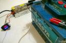
But first, a few illustrations. In all cases, TTI relays of the TRJ and TRIL series were used, and a 650 W vacuum cleaner was used as the load.
Classic scheme - we connect the vacuum cleaner through a regular relay. Then we connect an oscilloscope to the vacuum cleaner (Caution! Either the oscilloscope or the vacuum cleaner - or better yet, both - must be galvanically isolated from the ground! Don’t put your fingers or eggs in the salt shaker! They don’t joke with 220 V!) and take a look.
Include:
I had to reach almost the maximum mains voltage (trying to tie an electromagnetic relay to the zero crossing is a disastrous task: it is too slow). A short surge with almost vertical fronts boomed in both directions, and interference flew in all directions. Expected.
Turn off:
A sudden loss of voltage on an inductive load does not bode well - the surge will fly upward. In addition, do you see this noise on the sine wave milliseconds before the actual shutdown? This is the sparking of the relay contacts that have begun to open, which is why they will one day become stuck.
So, it is bad to switch an inductive load with a “naked” relay. What will we do? Let's try to add a snubber - an RC chain of a 120 Ohm resistor and a 0.15 µF capacitor.
Include:
Better, but not much. The ejection decreased in height, but was generally preserved.
Turn off:
Same picture. The debris remained, moreover, the sparking of the relay contacts remained, although greatly reduced.
Conclusion: with a snubber it is better than without a snubber, but it does not solve the problem globally. However, if you want to switch inductive loads with a regular relay, install a snubber. The ratings must be selected for a specific load, but a 1-W resistor at 100-120 Ohms and a capacitor at 0.1 µF seem to be a reasonable option for this case.
Related literature: Agilent - Application Note 1399, “Maximizing the Life Span of Your Relays.” When operating the relay on the worst type of load - a motor, which, in addition to inductance, also has a very low resistance at start - good authors recommend reducing the relay's rating life by five times.
Now let’s make a knight’s move - we will combine a triac, a triac driver with zero detection and a relay into one circuit.
What's in this diagram? On the left is the entrance. When “1” is applied to it, capacitor C2 is almost instantly charged through R1 and the lower half of D1; Optorelay VO1 turns on, waits for the nearest zero crossing (MOC3063 - with built-in zero detector circuit) and turns on triac D4. The load starts.
Capacitor C1 is charged through a chain of R1 and R2, which takes approximately t=RC ~ 100 ms. These are several periods of mains voltage, that is, during this time the triac will have time to turn on, guaranteed. Next, Q1 opens and relay K1 turns on (as well as LED D2, shining with a pleasant emerald light). The relay contacts bypass the triac, so then - until it turns off - it does not take part in the operation. And it doesn't heat up.
Switching off is in reverse order. As soon as “0” appears at the input, C1 is quickly discharged through the upper arm of D1 and R1, the relay turns off. But the triac remains on for about 100 ms, since C2 is discharged through the 100-kilo-ohm R3. Moreover, since the triac is held open by current, even after VO1 is turned off, it will remain open until the load current drops in the next half-cycle below the holding current of the triac.
Inclusion:
Shutdown:
Beautiful, isn't it? Moreover, when using modern triacs that are resistant to rapid changes current and voltage (all major manufacturers have such models - NXP, ST, Onsemi, etc., names begin with “BTA”), a snubber is not needed at all, in any form.
Moreover, if you remember the smart people from Agilent and look at how the current consumed by the motor changes, you get this picture:
The starting current exceeds the operating current by more than four times. During the first five periods - the time by which the triac is ahead of the relay in our circuit - the current drops by approximately half, which also significantly softens the requirements for the relay and prolongs its life.
Yes, the circuit is more complex and more expensive than a regular relay or a regular triac. But often it's worth it.
The advent of semiconductors had a huge impact on the development of electronics: overall dimensions, as well as the price of components, decreased significantly. Diodes and transistors began to be introduced everywhere. One of these industries was relay technology, which, thanks to semiconductors, significantly expanded its range of applications.
The use of semiconductors has led to the emergence of a new class of relay technology - solid-state relays (SSRs). So, if in electromechanical relays a mechanical contact was used to open (close) the circuit, then in a new class of devices this function was taken over by transistors and thyristors (triacs). This replacement made it possible to avoid a number of significant shortcomings of electromechanical relays, such as: contact bounce, the occurrence of an arc discharge during switching, high switching time and low reliability. In addition, the use of a strapping circuit made it possible to add “intelligence” to the relay, i.e. implement a number service functions: control of zero crossing, presence of status signal, etc. Moreover, all this has a fairly compact size. The use of semiconductors also made it possible to get away from electromagnetic isolation, replacing it with optoelectronic one, which made it possible to increase noise immunity.
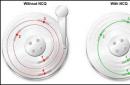
The presence of all these advantages has made it possible to use TTP in various industries. Thus, the possibility of organizing the operation of a relay not when the control signal passes through zero, but at its maximum (amplitude) value, has strengthened the role of SSRs for switching inductive loads. This process differs from switching an active load in that at the moment the signal is supplied, the transient process of establishing stationary mode electrical circuit in which the average current value over a period is zero. In this case, a constant component appears in the circuit for the duration of the transient process, which depends on the inductance and resistance of the circuit (circuit time constant τ=L/R) electric current(the circuit operates with bias during the transition process). The most undesirable moment of switching on is the moment the phase voltage passes through zero. In this case, the bias current and, accordingly, the amplitude of the current in the circuit has a maximum value. This mode can lead to saturation of the core (transformer, autotransformer, contactor winding, etc.). And as a result, a sharp decrease in inductance and, accordingly, a sharp increase in current (Fig. 1).
Figure 1 - transient process when the relay is turned on when the phase voltage passes through zero. τ is the time constant of the electrical circuit.
This can be avoided if you turn on the relay at the maximum amplitude Um) value of the alternating voltage (Fig. 2). As can be seen from the graph, this is achieved by shifting the phases of the current relative to the voltage by 90˚.

Figure 2 – transient process when the relay is turned on when the phase voltage passes through the maximum value of Um.
One of the options for solving this problem is to use a semiconductor optoelectronic single-phase relay alternating current RPT-90, switched on at the maximum (amplitude Um) value of alternating voltage, produced by the domestic company Proton-Impulse CJSC (Fig. 3). The relay is made in a monolithic housing with dimensions 58.4x45.7x23.

Figure 3 – Overall and connection dimensions of the module
The relay is designed to connect active and active-inductive loads (transformer, autotransformer, electromagnetic contactor, etc.) to an alternating current network with a frequency f=50-60Hz, voltage Ud=100-400V. An alternating voltage from 7 to 278 V can serve as a control voltage. The connection diagram is shown in Figure 4.

Figure 4 – Connection diagram for the RPT-90 relay
This relay is universal, has IP 54 protection and allows you to switch both active and inductive loads with a current of up to 63 A. Specifications relays are presented in table 1.
Table 1. Main parameters of RPT-90

Conclusions:
In addition to the listed advantages, SSRs have increased reliability and operating time, which makes the presented relay a universal solution for the problem of switching circuits for active and inductive loads.
KIPPRIBOR is a Russian manufacturer of solid-state relays (SSR). KIPPRIBOR solid-state relays provide reliable switching in the largest range of load currents in Russia today (up to 800 A), are structurally highly reliable (complete filling of elements with compound, copper base for efficient heat removal, automated production, special methodology for testing finished products). You can purchase KIPPRIBOR TTP from OWEN dealers.
The role of solid-state relays (SSR or in the English version SSR or TPPT accepted in the scientific world) in modern systems for switching electrical loads is significant. In recent years, in various technological areas (from automotive electronics, communication systems and consumer electronics to industrial automation), there has been a transition from building switching systems using conventional starters and contactors to convenient, reliable switching methods using semiconductor switches.
What you need to know about solid state relays? Where is it used and how is it designed? You will find answers to these questions in this section of our portal.
Solid State Relay (SSR) is a class of modern modular semiconductor devices made using hybrid technology, containing powerful power switches based on triac, thyristor or transistor structures. From the end user's point of view, thyristors and triacs are more of a component product, while a solid state relay is a complete and ready-to-use device. Few people know that in the scientific world solid-state relays are called Thyristor switches. Thyristor alternating current switches (ACTC) are the most widely used in industry. At some point in time, marketers came up with the name “Solid State Relay,” which, on the one hand, combined the two terms AC switches and DC switches into one common one, and on the other hand, this term became closer and more accessible to the general consumer. Ultimately, this term caught on and was accepted by specialists, and thyristor switches became widely used as power switching elements. In essence, a solid-state relay is a switching element based on a semiconductor element, but additionally incorporating a circuit for converting control signals from the semiconductor element into a signal convenient for use and application. In addition, the solid-state relay contains a number of design solutions that ensure reliability and ease of use. They are successfully used to replace traditional contactors and starters. Solid state relays provide the most reliable method of switching circuits. Performing the same functions, TTPs have a number of advantages:
- No moving parts;
- High reliability and long service life;
- Stability of characteristics throughout the entire service life;
- Absence of contact bounce and acoustic noise;
- Low power consumption and high performance;
- Small dimensions with high rated current values;
- Convenient housing for mounting on a radiator;
- More low level interference generated during switching.
A standardized relay housing type and an assortment of specialized cooling radiators relieve the user of design concerns when placing equipment at the site of operation.
Along with the advantages, there are also some inconveniences when using SSRs: heat generation in operating mode, which is typical for any semiconductor device, and a slightly higher cost compared to equivalent models of electromechanical relays and contactors. However, thanks to an almost endless service life and the elimination of equipment downtime, TTPs pay for themselves in a relatively short period of time. And the issue of heating the relay is easily solved by using standard models of cooling radiators. In addition, there are special series of solid-state relays with the technology of applying a semiconductor switch directly to the relay substrate (SCR-type output), which provides an unprecedented improvement in heat dissipation performance and operational reliability in general.
KIPPRIBOR solid-state relays offer a wide range of modifications for switching both low and high load currents, as well as special series for performing specific switching tasks. KIPPRIBOR TTP provides reliable galvanic isolation of input and output electrical circuits from each other, as well as current-carrying circuits from the design elements of the device, so the use of additional circuit insulation measures is not required. Galvanic isolation implies the complete absence electrical connections between the input and output circuits and is carried out through the use of “optocouplers”, which make it possible to transmit a control signal using the optical method.
The exception is the HD-xx44.VA relay modification, which regulates the output voltage by controlling a variable resistor. This is due to the circuit design of the relay.
Modifications of solid state relays (SSR) KIPPRIBOR
Single-phase SSRs KIPPRIBOR
- Series KIPPRIBOR MD-xx44.ZD3- single-phase solid-state relays in a miniature housing specifically for switching low-power resistive or weakly inductive loads. Today, this is the most budget-friendly version of single-phase SSRs in Russia. Can be used in single-phase or three-phase network.
- KIPPRIBOR HD-xx44.ZD3 and HD-xx44.ZA2 series- single-phase general industrial solid-state relays in a standard housing for switching the most common industrial current ranges of resistive or inductive loads. Can be used in a single-phase or three-phase network.
- Series KIPPRIBOR HD-xx25.DD3- single-phase solid-state relays for switching DC circuits of resistive or inductive loads. Also, this series of SSRs is used to amplify the output signal of a control device (with a small output load capacity) when several SSRs are connected to it. Can be used in a single-phase or three-phase network.
- KIPPRIBOR HD-xx44.VA, HD-xx25.LA and HD-xx22.10U series- single-phase solid-state relays for continuous voltage regulation in the range from 10 V to the nominal value, proportional to the input signal. Recommended only for switching resistive loads. Can be used in a single-phase or three-phase network.
Types of control signals:- variable resistor 470 kOhm, 0.5 W for HD-xx.44VA;
- unified current signal 4…20 mA for HD-xx25.LA;
- unified voltage signal 0…10 V for HD-xx.2210U.
- KIPPRIBOR HDH-xx44.ZD3 series- single-phase solid-state relays for switching powerful loads, made in a standard TSR package. Allows you to switch resistive or inductive loads in a single-phase or three-phase network.
- KIPPRIBOR SBDH-xx44.ZD3 and BDH-xx44.ZD3 series- single-phase solid-state relays for switching powerful loads, made in industrial standard housings. Used for switching power circuits of powerful resistive or inductive loads in a single-phase or three-phase network. The housing has large terminals for convenient connection of large cross-section wires. The SBDH series SSR is made in a more compact package.
- Series KIPPRIBOR GaDH-xxx120.ZD3- with enhanced heat dissipation GwDH-xxx120.ZD3 with water cooling - single-phase SSR. They cover the largest range of load currents in Russia today. They are used for switching power circuits of powerful resistive or inductive loads in a single-phase or three-phase network, providing a guaranteed flow margin.
Three-phase SSRs KIPPRIBOR
- KIPPRIBOR HT-xx44.ZD3 and HT-xx44.ZA2 series three-phase solid-state relays for switching resistive loads. Provide simultaneous switching for each of the 3 phases. Can be used for group switching of loads in three single-phase circuits.
The heating of solid-state relays when switching a load is caused by electrical losses on the power semiconductor elements. An increase in the temperature of the SSR imposes a limitation on the amount of switched current, since the higher the temperature of the solid-state relay, the less current it can switch. Reaching a temperature of 40° C does not cause a significant deterioration in operating parameters, and heating the solid-state relay to 70° C significantly reduces the permissible value of the switched current: the load may not be completely switched off, and the SSR itself may go into an uncontrolled operating mode and even fail.
Consequently, during long-term operation of a solid-state relay in nominal, and especially “heavy” modes (during long-term switching at load currents above 5 A), the use of radiators or air cooling is required to dissipate heat. For increased loads, for example, in the case of inductive loads (solenoids, electromagnets, etc.), it is recommended to choose a solid-state relay with a large current reserve (2-4 times), and in the case of using solid-state relays to control an asynchronous electric motor, it is necessary 6-10 times the current reserve.
When working with most types of loads, turning on a solid-state relay is accompanied by a current surge (inrush overload) of varying duration and amplitude, and this must be taken into account when choosing a solid-state relay.
For various types loads, you can specify the following starting overload values:
- purely active loads (heaters such as heating elements) give the minimum possible current surges (up to 25% of the nominal), which are practically eliminated when using a solid-state relay with switching at zero;
- incandescent lamps, halogen lamps, when turned on, pass a current 7...12 times more than the rated current;
- fluorescent lamps during the first seconds (up to 10 seconds) give short-term current surges, 5-10 times higher than the rated current;
- mercury lamps give a triple current overload during the first 3-5 minutes;
- alternating current electromagnetic relay windings: current is 3...10 times higher than the rated current for 1-2 periods;
- solenoid windings: current is 10...20 times higher than the rated current for 0.05 - 0.1 sec;
- electric motors: current is 5…10 times higher than the rated current for 0.2 - 0.5 sec;
- highly inductive loads with saturable cores (transformers at no-load) when turned on in the zero-voltage phase: the current is 20-40 times higher than the rated current for 0.05 - 0.2 sec;
- capacitive loads when switched on in a phase close to 90°: the current is 20-40 times higher than the rated current for a time from tens of microseconds to tens of milliseconds.
The ability of solid-state relays to withstand current overloads is characterized by the magnitude of the shock current, i.e. the amplitude of a single pulse of a given duration (usually 10 ms). For direct current relays, this value is usually 2–3 times greater than the maximum permissible direct current; for thyristor relays this ratio is about 10. For current overloads of arbitrary duration, we can proceed from the empirical relationship: an increase in the overload duration by an order of magnitude leads to a decrease in the permissible current amplitude.
The choice of the rated current of a solid-state relay for a specific load consists of selecting a margin for the rated current of the relay and introducing additional measures to reduce inrush currents (current-limiting resistors, reactors, etc.).
The algorithm for selecting a solid-state relay can be reduced to three main steps:
- We determine the necessary modification of the relay based on the type of supply voltage (single- or three-phase, direct or alternating current), the required type of control signal (discrete direct or alternating current, or analog).
- We select the required value of the relay current based on the condition that the solid-state relay current must exceed the value of the load current in any operating mode; in other words, when choosing the relay current, we are guided not by the rated load current, but by the starting current, starting current, etc. For example, for a heater the starting current is 10% higher, which means that when choosing, we are guided by 30 - 40% greater than the nominal value (10% starting current of the heater, 20% voltage fluctuation in the network). But for an incandescent lamp, the starting current, as already mentioned, is 10–12 times higher, which means we select a relay with a current 12 times greater than the rated one.
- We select the required cooling radiator for the selected solid-state relay, based on the rated operating current of the load connected to the relay. When choosing a radiator, it is also better to use the radiator selection table given on our website. Please take into account the factors that impair heat dissipation and deliberately choose a radiator with a margin of power dissipation.
To increase the solid-state relay's resistance to impulse noise, there is a circuit in parallel to the switching contacts in the SSR consisting of a resistor and capacitor connected in series (RC circuit).
For more complete protection from a source of overvoltage on the load side, it is necessary to include protective varistors in parallel with each phase of the solid-state relay, and in the case of SSRs that switch direct current, a protective diode.
For more information about the RC circuit, the rules for selecting a varistor and diode, see below.
Radiators of the RTR series for solid-state relays KIPPRIBOR
A solid-state relay heats up when current flows through it in the load circuit, this is due to electrical losses on the power semiconductor elements. In this case, an increase in the temperature of the relay imposes a limitation on the amount of load current it switches. In order to cool the SSR, the switching element in all KIPPRIBOR solid-state relays is mounted on a metal base of the housing, onto which the heat generated during operation is dissipated. However, the metal base of a solid-state relay, due to its small area, is capable of successfully dissipating only a small amount of heat when the load current does not exceed 5A. Consequently, during long-term operation of the relay with load currents above 5A, additional cooling measures are required. The most obvious way to improve the heat dissipation of a relay is to increase the heat dissipation area from the metal base of the relay. This can be achieved by installing a solid-state relay on the cooling radiator.
The load current value indicated on the solid-state relay nameplate is indicated based on the condition that the relay base is heated to no higher than 40°C. The higher the relay heating temperature, the less current it can switch. When the relay heats up above 40°C, the permissible value of the switched current decreases and will be less than the value stated on the relay nameplate. At 70°C, the switching capacity of the relay drops by half. And when heated to 80°C, thermal overheating of the switching switch already occurs with the relay transitioning to an uncontrolled mode, when the load is turned on using the SSR, but can no longer be turned off. As a result, this leads to thermal breakdown of the switching element and, accordingly, failure of the relay. Obviously, for normal operation of a solid-state relay, it is necessary to ensure heat removal from the switching element in order to avoid overheating of the relay with subsequent failure.
In addition, operating the relay at elevated temperatures (over 60 degrees) reduces the service life and increases the likelihood of the relay failing for other reasons.
If the ambient temperature is elevated (over 40°C), the SSR will not be able to cool properly, even when using a radiator with forced airflow. In such a situation, the SSR will overheat and may fail. In this case, two solutions are possible:
- provide power cabinets with external cooling (air conditioners);
- use water-cooled SSR of the GwDH series.
The use of the standard TTR series at elevated temperatures and without external air conditioning is possible, provided that the rated current of the relay is selected taking into account its elevated operating temperature.
MAIN RULE FOR CHOOSING A RADIATOR
When choosing a heatsink for cooling a solid-state relay, you should be guided by:
- first of all, the ability of the radiator to dissipate heat (!);
- and only then pay attention to the dimensional characteristics.
MAIN RULE FOR RADIATOR INSTALLATION
The installation of the cooling radiator at the place of application must be carried out in such a way that its cooling fins are parallel to the air flows: in the absence of forced ventilation - vertically, along the flow of natural air circulation (bottom-up), or in any position in the presence of forced airflow using a cooling fan . Installation of all models of RTR radiators is carried out on a plane with screws.
Particular attention should be paid to installing the solid-state relay on the radiator and using heat-conducting paste.
Mounting a Solid State Relay on a Radiator
For different series of solid-state relays, RTR series radiators have different mounting holes. The types of relays allowed for installation on a specific radiator are indicated in the characteristics of the radiator.
When installing the TSR on a radiator, it is necessary to use heat-conducting paste. Thermally conductive paste is usually a silicone-based paste that has good thermal conductivity. It is used in electronic devices to improve the process of heat removal from components mounted on a radiator. The use of thermally conductive paste when mounting a solid-state relay on a cooling radiator significantly improves heat transfer from the relay to the radiator. The heat transfer efficiency is increased by filling small voids between the surfaces of the relay and the radiator, i.e. by compensating for roughness and defects of the contacting surfaces. The most common brand of heat-conducting paste on the Russian market is KPT-8 brand paste with an operating temperature from –60 to +180 °C. An alternative option is the thermal conductive plate used by some SSR manufacturers. However, do not forget that thermal conductive paste improves heat dissipation performance only if it is applied correctly.
When applying thermally conductive paste to a solid-state relay, attention should be paid to maintaining the optimal thickness and uniformity of the applied layer. A layer of thermally conductive material that is too thick increases the thermal resistance of the heatsink-to-relay junction and prevents normal heat dissipation from the solid-state relay. An uneven layer leads to the formation of even more air voids between the surfaces of the relay and the radiator and sharply increases the thermal resistance of the junction. A layer of thermal conductive paste up to 40 microns is considered optimal, when the surface structure of the radiator is visible through the layer of thermal paste, since this is quite enough to cover surface roughness. It is advisable to apply the paste to the radiator using an even metal spatula, ensuring that the paste is distributed in proportion to surface defects. Applying paste to the radiator is more effective due to the greater unevenness of its surface compared to the base of the relay. After installing the relay on a radiator with thermal paste applied, it is necessary to “grind in” the surfaces. Grinding is performed with small oscillatory movements (up to 5 mm, but without mutual separation of the surfaces!) while simultaneously pressing the relay onto the radiator. Only after this can the relay be fixed to the radiator with screws.
SELECTION of radiators for a specific TTR series
Accurate calculation of the required cooling radiator for a specific application of SSR requires a large number of mathematical calculations. However, most applications of solid-state relays are typical (installation in a vertical cabinet, load - heating elements). In this case, you can simplify the choice of radiator using Heatsink selection table for KIPPRIBOR solid-state relays, which you will find on our website in the section Heatsinks for Solid State Relays.
However, it is worth considering that the radiator selection tables are developed based on the normal operating conditions of the TSR, when the operating temperature does not exceed 25 ° C, and the radiator is installed in a well-ventilated place where nothing interferes with the natural circulation of air. Therefore, when choosing according to the selection tables, you should definitely take into account factors that worsen heat transfer (placement in a cabinet, increased external temperature at the installation site, etc.), and choose a radiator with a margin of power dissipation. It must be remembered that in order to avoid unnecessary expenses, the radiator is selected based on the rated continuous load current, and not the current for which the SSR is designed. KIPPRIBOR RTR cooling radiators are presented in several models, differing in dimensional and technical characteristics and the amount of power dissipation. If the task is to use a KIPPRIBOR solid-state relay with a cooling radiator from a third-party manufacturer, then it will be necessary to carry out a thermal calculation to select the required type of radiator. In this case, the initial data and calculation methodology must be requested from the cooling radiator manufacturer
Cm. detailed description solid state relays KIPPRIBOR series:
special series of single-phase TSRs: HD-xx25.DD3 | HD-xx44.VA, HD-xx22.10U and HD-XX25.LA
TSR with enhanced heat dissipation: GaDH-xxx120.ZD3 and GwDH-xxx120.ZD3
General classification of KIPPRIBOR solid-state relays (SSR) by switched network type
Solid state relay for switching single-phase network:
- can be used to switch a three-phase network using one single-phase solid-state relay per phase;
- allow switching of three-phase loads with any connection circuit (“Star”, “Star with neutral” and “Triangle”). The use of a separate solid-state relay for switching each of the 3 phases significantly increases the reliability of switching due to more optimal cooling of the relay of each phase, and, consequently, the reliability of the entire control system as a whole;
- allow you to switch resistive and inductive loads;
| Three-phase load | |||
| "star" | "star with neutral" | "triangle" | |
 |
 |
 |
|
In solid-state relays for switching a three-phase network, all three switching elements are controllable. These relays allow:
- switch loads with any connection circuit (“Star”, “Star with neutral” and “Triangle”) or control three groups of single-phase loads;
- switch loads only of resistive type
| Three-phase load | |||
| "star" | "star with neutral" | "triangle" | |
 |
 |
 |
 |
Leakage currents in the circuit as applied to solid state relays
In general leakage current- This is the current that flows into the ground or to third-party conductive parts in an intact electrical circuit.
Applied to solid state relays leakage current- this is the current present in the load circuit, even when there is no control voltage on the solid-state relay. The leakage current in a solid-state relay is due to the presence of a load circuit built in parallel RC chains, through which, when voltage is applied to the SSR, current always flows, even when the switching element of the solid-state relay is in "off state". The presence of a constant, albeit small, leakage current imposes some restrictions on the operation of solid-state relays; in particular, it is necessary to observe safety measures during adjustment work and turn off the power to the load circuit.

RC chain (snubber RC chain)
RC chain(snubber RC circuit) - an electrical circuit consisting of a series-connected capacitor (capacitor) and resistance (as applied to solid-state relays). The ratings of the circuit elements are usually C = 0.1 μF, R = 50 Ohm. The RC chain increases the reliability of SSR operation under conditions of impulse noise (overvoltage) and limits the rate of voltage rise on the switching element, which is especially important when switching an inductive load. Quite often, an RC circuit is called an anti-aliasing filter or a snubber circuit.
As mentioned above, the RC circuit built into the relay leads to the appearance of leakage current in the load circuit. The magnitude of this current is very small and does not have any effect on the powerful load, but this current is quite sufficient for the multimeter to indicate the presence of voltage on the load connected to the relay.
Types of solid state relay loads. General classification
Solid-state relays from various manufacturers are oriented primarily to control resistive or weakly inductive loads, the power factor of which (cos φ) is not lower than 0.7. Typically these are heating elements of various designs and incandescent lamps. In the KIPPRIBOR line of solid-state relays these include the series M.D., HD, HT. In order to reduce the level of noise generated when switching a load, these types of relays usually have a zero-crossing control circuit, that is, they switch (on and off) at zero of the voltage sinusoid when the switched currents are small.
Along with standard series, in the KIPPRIBOR line there are special series of solid state relays HDH, BDH, SBDH, GaDH, GwDH made with SCR type output. These series SSRs can be used to control inductive type loads whose power factor (cos φ) is greater than 0.5, such as low-power on-load electric motors, solenoids, valve coils, etc. These series of relays are also suitable for controlling resistive loads. Relays of this type also have a switching control circuit at zero voltage sinusoid and create a minimal level of noise. For highly inductive loads whose power factor (cos φ) is less than 0.5 (for example, no-load transformers and some types of electric motors), the use of solid-state relays is associated with many nuances. In particular, it is necessary to use a relay with a random (instantaneous) switching circuit. In the KIPPRIBOR line of such relays there are this moment is not provided, and switching highly inductive loads using existing SSRs is not recommended.
– an electrical load in the form of a resistance (resistor), which converts electrical energy into thermal energy. Such a load is characterized by an almost complete absence of reactive power, and the power factor (cos φ) is usually close to 1.0.Most heaters (heating elements) are resistive loads. Resistive loads are characterized by relatively low inrush currents, which makes it possible to use solid-state relays for switching resistive loads with a minimum current margin (usually a margin of 30...40%), which covers errors in the rated power of the heater itself (±10%), an increase in power of cold state (±10%) and possible fluctuations in the mains supply voltage (±15%). But there are exceptions, a striking example is incandescent lamps. They have a filament, which acts as a resistance and during operation heats up to a high temperature, causing a glow. However, the relay selection algorithm for incandescent lamps differs from that for heaters. The fact is that although the filament of an incandescent lamp is essentially a resistive load, it has quite high starting currents - up to 12 times the rated value. This is due to the very large spread in the resistance of the nichrome filament of the lamp in the cold and hot states. Therefore, when choosing a solid-state relay for an incandescent lamp, it is necessary to make a choice based on the following calculation: relay current = lamp current × 12.
heating element– a heater in the form of a metal tube filled with a heat-conducting electrical insulator, in the center of which a heating element of a certain resistance is installed. A nichrome thread is usually used as a heating element. The heating element refers to a resistive type load with low inrush currents.
– electrical load with a large inductive component.The inductive load includes all consumers where there is active and reactive power, and the power factor (cos φ) is less than 1.0, or, in simple words, any load that contains electric coils or windings: valve solenoids, transformers, electric motors, chokes, etc. A characteristic feature of an inductive load is the high current consumption when it is turned on (inrush currents) caused by transient electrical processes in the coils and windings . The inrush current values of an inductive load can exceed the rated current by several tens of times and can be quite long in time, therefore, when using solid-state relays to switch an inductive load, it is necessary to select the SSR rating taking into account the load inrush currents. You can find out the exact value of the starting current of the applied load from the equipment manufacturer or estimate it from open sources for similar equipment.
Classification of KIPPRIBOR solid-state relays (SSR) by range and type of switching voltage
The KIPPRIBOR line of solid-state relays includes modifications for use in DC and AC circuits.
Standard switching range for KIPPRIBOR SSR with discrete control
| Switched network type | Modifications | Switching range |
| alternating current | MD-xx44.ZD3 | 24…440 VAC |
| HD-xx44.ZD3/ZA2 HDH-44.ZD3 SBDH/BDH-xx44.ZD3 HT-xx44.ZD3 |
40…440 VAC | |
| GaDH/GwDH-xxx120.ZD3 | 60…1000 VAC | |
| D.C. | HD-xx25.DD3 | 12…250 VDC |
Standard voltage switching range of specialized relay modifications:
It is worth noting that a relay designed to operate in AC circuits (all modifications of the KIPPRIBOR TSR, except for the HD-xx25.DD3 modification) will not be able to control the load in a DC circuit. In this case, the relay will initially turn on the load, but will not be able to turn it off, since to close the semiconductor switch it is necessary to reduce the voltage / current to zero, but this will not happen in a DC circuit.
As well as vice versa: KIPPRIBOR solid-state relays for controlling a load in a DC circuit (modification HD-xx25.DD3) cannot be used to control AC circuits, since they use transistors as a switching element, and connecting them to an AC circuit will lead to to relay failure.
Voltage class- applied to semiconductor devices(thyristors) means: the maximum permissible value of the repeating pulse voltage in the closed state and the maximum permissible value of the reverse voltage applied to the semiconductor element. The voltage class is usually marked with numbers in the form of the number of hundreds of volts, for example, the 9th voltage class will mean that this semiconductor element can withstand a maximum peak voltage of 900 Volts, but the rated operating voltage should not exceed 440V (380V power supply).
For a power supply network with a rated voltage of 220 Volts, it is recommended to use semiconductor elements of at least voltage class 9, i.e. they must be able to withstand a maximum peak voltage of 900 volts.
Most modifications of KIPPRIBOR solid-state relays (HD, HDH series) have a permissible switching voltage range of up to 440 V, which is achieved by using semiconductor switching elements with a voltage class of at least 9 (900 Volts). For a power supply network with a rated voltage of 380 V, provided that varistors are used for surge protection, it is allowed to use semiconductor elements of at least 9th voltage class.
For switching large load powers, there are series of relays BDH, SBDH, GaDH and GwDH, which have switches of an even higher voltage class - 11 and 12 and 16 classes, which allows them to be used in difficult industrial conditions with a supply voltage of up to 1000 Volts.
Specialized modifications of TSR (with indices in the designation ... 10U, ... LA), designed for a maximum permissible operating voltage of 220 ... 250 V, contain semiconductor switches of voltage class 6 ... 9 and are not intended for use in load circuits with a power supply of 380 V The general industrial series of KIPPRIBOR solid-state relays have voltage class 9.
Classification of KIPPRIBOR solid-state relays by type of control signal
Depending on the modification, KIPPRIBOR solid-state relays can have the following types of control signals:
- DC control voltage 3...32 V – modifications with index ...ZD3;
- AC control voltage 90…250 V – modifications with index …ZA2;
- DC control voltage 5…32 V – modifications with index …DD3;
- manual control of the output voltage using a variable resistor (470-560 kOhm, 0.25-0.5 W) - modifications with the ...VA index;
- analog control of output voltage using a unified voltage signal 0...10 V - modifications with the index ...10U;
- analog control of the output voltage using a unified current signal 4...20 mA - modifications with the index ...LA.
Various options for control signals allow the use of KIPPRIBOR solid-state relays as switching elements in various types of automatic control systems.
For more information on applications of solid state relays, see Applications of Solid State Relays.
Classification of KIPPRIBOR solid-state relays by switching method
Solid State Relays with Zero Crossing Monitoring
This type of relay is usually designated by the letter Z, which is short for English word Zero (translated as “zero”). All series of KIPPRIBOR solid-state relays (MD, HD, HDH, HT, BDH, SBDH, GaDH, GwDH), with the exception of specialized modifications, belong to this type of SSR.
When a control signal is applied to a relay of this type, voltage appears in the load circuit only at the moment the sinusoidal voltage first crosses the “zero” level. This is clearly shown in the figure.

Advantages of relay of this type are a lower initial surge of current in the load circuit when turned on, a low level of generated electromagnetic interference and, as a result, an increased service life of switched loads.
The disadvantage of relays of this type is the limited use of them for switching inductive loads, in the case where cosφ
Solid State Relays with zero crossing control used for switching:
- resistive loads: electric heating elements (heating elements), incandescent lamps, etc.
- capacitive loads: for example, noise-suppressing smoothing filters containing capacitors;
- weakly inductive loads: solenoid coils, valves, etc.
Solid state relays instantaneous (random) activation
This type of relay, as a rule, has the letter R in its designation, this is an abbreviation for the English word Random (translated as “random”). The KIPPRIBOR product line currently does not include a relay of this type.
The voltage in the load circuit of a relay of this type appears simultaneously with the supply of a control signal (on delay time is no more than 1 ms), and the relay can be turned on at any section of the sinusoidal voltage. This is clearly shown in the figure.

Solid state relays instantaneous (random) activation used for switching:
- resistive (electric heating elements, incandescent lamps);
- and inductive (low-power motors, transformers) loads when instantaneous operation is required.
Phase Control Solid State Relays
Phase Control Solid State Relays allow you to change the output voltage at the load and are used for the following tasks:
- regulation of the power of heating elements,
- adjust the light level of an incandescent lamp, etc.
This type includes KIPPRIBOR relays controlled using a variable resistor (modification HD-xx44.VA), a unified current signal 4...20 mA (modification HD-xx25.LA) and a unified voltage signal 0...10 V (modification HD- xx22.10U).
The voltage value in the load circuit of a relay of this type depends on the value of the signal in the control circuit and is proportional to its value. This is clearly shown in the figure.

Types of output power elements of KIPPRIBOR solid state relays
KIPPRIBOR solid-state relays, depending on the modification, can have one of four power elements as an output switch:
- triac output (TRIAC)– used in relays of the MD, HD, HT series of all modifications with a current of up to 40A (except for modifications with the DD3 index);
- transistor output (Transistor)– used in relays of the HD series modification DD3;
- SCR output (SCR)– used in relays of the HDH, BDH, SBDH, GaDH, GwDH series of all modifications and relays of the HT-xx44.ZD3 series with a current of 100A or more;
- thyristor output (Thyristor)– used in relays of the HD and HT series of all modifications with a current of over 40A.
Triac outputs are used in solid-state relays with rated currents up to 40 A inclusive. A reasonable current limit of 40A is due to the fact that when a larger value of current flows on both sides, effective heat removal from the triac crystal cannot be achieved. Relays of the MD, HD and HT series with rated currents up to 40A have a triac output.
Thyristor output elements are used in solid-state relays for currents from 60A. Separately installed on the cooling substrate, they significantly reduce the thermal resistance coefficient of the relay as a whole, which makes it possible to ensure the necessary heat dissipation.
SCR type output is used in single-phase series of KIPPRIBOR relays with load currents over 60–80A. Symbol SCR is the generally accepted international name for a semiconductor switch based on a triode thyristor (or simply thyristor). The SCR output in relation to the KIPPRIBOR solid-state relay designates the type of semiconductor switch design, when an insulating ceramic substrate with single crystals of the semiconductor structure directly deposited on it is placed on the metal base of the relay.
The SCR output allows you to significantly reduce the thermal resistance of the relay substrate and improve the heat dissipation characteristics. Therefore, relays of this type have improved performance characteristics compared to solid-state relays made using conventional housing elements (thyristors and triacs).
Relays of this type are designed for operation in more difficult operating conditions in the presence of fast transient processes in the power supply network: operation in a network with a high level of noise, operation of an inductive load, operation in conditions of high load current surges.
However, this does not exclude the requirement to use radiators and cooling fans to operate with high switching currents.
In modifications of KIPPRIBOR solid-state relays, designed for long-term switching of high currents or operation with inductive loads, thyristor SCR outputs are used.
Protection of TSR circuits.
Varistor. Rule for selecting a varistor for a solid-state relay
Varistor– a semiconductor element whose resistance depends on the voltage applied to it. Due to a sharp decrease in its resistance when a certain voltage level is exceeded, such an element can be used as a voltage limiter in electrical circuits. In relation to a solid-state relay, a varistor is used to protect the solid-state relay itself from exceeding its permissible overvoltage level. High levels of overvoltages are characteristic of power networks with inductive and capacitive loads, which generate interference into the network from electrical transients occurring in them. The most common are metal oxide varistors (MOVs).
One of the main parameters by which a varistor is selected is the classification voltage of the varistor; this is a conventional voltage value, after which a sharp change in the resistance of the varistor occurs. Therefore, to select a varistor, it is necessary to determine the rated supply voltage of the load (permissible relay voltage) and calculate the classification voltage of the varistor using a simplified formula:
U varistor = U operating × (1.6...1.9).
For example, if the operating voltage of the load supply is 230 V, and the permissible operating voltage of the relay is 440 V, then a voltage varistor is recommended:
U varistor = 230 × (1.6…1.9) = 368…437V.
Since varistors are manufactured with a strictly defined range of classification voltages, you should select the closest suitable voltage from the range, in this case 390 V.
In particularly difficult industrial operating conditions, with a large number of transient processes in the network and a high level of overvoltages, when choosing a varistor, you must proceed from the rule:
U varistor
Since the energy released by the varistor during short peak overloads is usually small, in most cases any type of varistor can be used for industrial purposes. The most common series of domestic varistors are: CH2-1, CH2-2, VR-1, VR-2.
However, it is always recommended to select a varistor with the highest possible energy dissipation value. Typically, the larger the diameter of the varistor housing, the greater the amount of energy dissipated it provides. Most varistors are manufactured in a small round case with wire leads, which allows it to be successfully mounted directly onto the SSR terminals.
Rule for selecting a protective diode for SSR HD-xx25.DD3
When using the HD-xx25.DD3 SSR to switch an inductive load, the SSR output must be protected from self-induction voltage. The most inexpensive and common method of such protection is to install a shunt diode in parallel with the inductive load. In steady state, the diode has no effect on the operation of the circuit. When the load is turned off, when a self-inductive voltage occurs that is opposite in polarity to the operating voltage, the diode opens and shunts the inductive load.
Diode selection rule:
- The operating current and reverse voltage of the diode should be comparable to the rated voltage and current of the load. For the HD-xx25.DD3 STR, a 1N5399 silicon diode with a maximum reverse voltage 1000 VDC and maximum pulse current up to 50 A;
- The diode leads should be as short as possible;
- The diode leads should be connected directly to the load;
- When connecting the diode to the load, do not use long connecting wires.
Design features of solid-state relays (SSR) KIPPRIBOR
Solid State Relay Base- this is a heat-conducting metal base of a solid-state relay, necessary to remove heat from the switching element of the SSR to the cooling radiator. Can be made of aluminum or copper alloy.
The solid state relay base material can be distinguished visually: the aluminum alloy base has a matte pale gray color, while the copper alloy base resembles the appearance of brushed steel, and can sometimes have an almost mirror-like polished surface. The copper base has an unusual mirror-steel appearance due to its coating with an additional layer of nickel, which eliminates the oxidation of copper during long-term or improper storage.
Copper alloy TTR base- the most efficient for solid-state relays in terms of heat transfer. Since the thermal conductivity of copper is much higher than that of aluminum, the process of heat removal from the switching element of the TSR occurs much faster and more efficiently. Therefore, an SSR with a copper base (as opposed to a relay with an aluminum base) more effectively withstands peak loads and operates more efficiently in difficult operating conditions, but copper has a slightly higher cost compared to aluminum.
Aluminum alloy base- cheaper. Since the aluminum base of a solid-state relay is less efficient compared to copper, it is used in budget product series and exclusively for switching small loads.
Diagnostic methods and characteristic nuances of TTP operation
Possibility of checking SSR power circuits with a multimeter
The switching semiconductor switch in the SSR is equipped with additional shunt circuits, including an RC circuit, so it will not be possible to check its serviceability using measurements with a multimeter. Under no circumstances should you try to check the serviceability of the relay with a megohmmeter or an insulation tester, since such devices generate a high-level measuring voltage and will lead to breakdown of the SSR semiconductor switch. It is best to check the serviceability of a solid-state relay by directly connecting a load to it, for example, a low-power incandescent lamp. If the TT is correct, then after the control signal is applied, the lamp will burn at full intensity, and when the control signal is removed, it will go out completely.
Ability to test SSR control circuits
All KIPPRIBOR brand solid-state relays have a built-in LED indication of the presence of a control signal, with which you can quickly assess the health of the control circuit. There is no need to resort to additional diagnostic measures for the TSR control circuit.
Thermal overheating and thermal breakdown of SSR
You can check whether the relay is overheating or thermal breakdown in the following way: disconnect the relay from the load, wait for the relay to cool completely, then, without applying a control signal to the relay, connect an incandescent lamp to it and apply power to the load circuit. If the lamp burns at half heat or at full power, this will indicate the presence of a breakdown in one or two switching elements of the relay.
How to check the sufficiency of the measures taken to cool the turbocharger?
You can check the correct cooling mode of the SSR by measuring the temperature of the relay base (metal plate of the housing) at the points of attachment to the radiator. If the temperature is close to 60 °C or exceeds this value, then the cooling for the relay is insufficient and additional measures must be taken to improve heat dissipation. It is best to diagnose a relay using a non-contact thermometer (pyrometer).
The solid state relay turns on but does not turn off the load, what is the reason?
In most cases, the cause is an attempt to use an SSR designed for AC voltage with a DC power supply (see KIPPRIBOR Solid State Relay (SSR) Classification by Switching Voltage Range and Type). Otherwise, there is a breakdown of the TSR switching switch, and the presence of one half-wave of the mains voltage is usually observed at the load, i.e., the voltage at the load is present, but it is half less than the nominal value. This situation is a consequence of a breakdown of one of the switching elements of the TSR. The situation when both switching keys are broken at once is less common. The most likely causes of relay breakdown are:
- large current surges in the load circuit, exceeding the permissible limits of the load capacity of the SSR, for example, when the starting currents were not taken into account when choosing a relay and the relay was selected only on the basis of the rated load current;
- the presence of a large level of interference (overvoltage) of the power supply network as a result of transient processes occurring, for example, when switching other powerful inductive loads on the same power supply line;
- thermal breakdown occurs when overheating of the relay leads to a decrease in the permissible switching current and subsequent breakdown of the switching element due to overload; or when the critical temperature for TTP is exceeded ~80°C. Less often, a situation occurs when the relay is not yet damaged and thermal overheating of the SSR occurs. In this case, the functionality of the relay can be restored after the relay cools down to acceptable temperature values. This situation occurs when the measures taken to cool the relay during operation are insufficient;
- insufficient air ventilation at the installation site of the TTR due to the presence of obstacles to the free movement of air (cabinet is too small, ventilation holes are blocked, etc.); HT-xx44.ZD3 and HT-xx44.ZA2
You can purchase KIPPRIBOR TTP from OWEN dealers. You can view the list of OWEN dealers
Go to the KIPPRIBOR solid state relay catalog TTR catalogue...>>
You can ask questions about TTP on the OWEN company forum forum...>>
Official partner of KIPPRIBOR in Russia -
What happens if you open a switch that controls current through an inductance? Inductance, as is known, is characterized by the following property: U = L(dI/dt), and from this it follows that the current cannot be turned off instantly, since in this case an infinite voltage would appear across the inductance. In fact, the voltage across the inductance increases sharply and continues to increase until current flows. Electronic devices that drive inductive loads may not be able to handle this voltage increase, especially components that experience breakdown at certain voltage levels. Consider the diagram presented
Rice. 1.94. Inductive "throw".
in Fig. 1.94. IN original condition the switch is closed and current flows through the inductance (which can be, for example, a relay winding). When the switch is open, the inductance tends to cause current to flow between points A and B in the same direction as when the switch is closed. This means that the potential of point B becomes more positive than the potential of point A. In our case, the potential difference can reach 1000 V before an electric arc occurs in the switch, which closes the circuit. In this case, the service life of the switch is shortened and impulse noise occurs, which can affect the operation of nearby circuits. If we imagine that a transistor is used as a switch, then the service life of such a switch is not shortened, but simply becomes zero!
To avoid such troubles, it is best to connect a diode to the inductance, as shown in Fig. 1.95. When the switch is closed, the diode is reverse biased (due to the drop in DC voltage across the inductor winding). When the switch opens, the diode opens and the potential of the switch contact becomes higher than the potential of the positive supply voltage by the amount of the voltage drop across the diode. The diode must be selected so that it can withstand an initial current equal to the current flowing in steady state through the inductance; suitable, for example, a diode like 1N4004.

Rice. 1.95. Inductive surge blocking.
The only drawback of the described circuit is that it delays the attenuation of the current flowing through the coil, since the rate of change of this current is proportional to the voltage across the inductance. In cases where the current must decay quickly (for example, high-speed contact printers, high-speed relays, etc.), the best result can be obtained if a resistor is connected to the inductor, choosing it so that the value of U and + IR does not exceed maximum permissible voltage on the switch. (The fastest decay for a given maximum voltage can be obtained by connecting a Zener diode to the inductor, which provides linear rather than exponential decay.)

Figure 1.96. RC “damper” to suppress inductive surge.
Diode protection cannot be used for AC circuits containing inductors (transformers, AC relays), since the diode will be open during those half-cycles of the signal when the switch is closed. In such cases, it is recommended to use the so-called RC damping chain (Fig. 1.96). The R and C values shown in the diagram are typical for small inductive loads connected to AC power lines. A damper of this type should be provided in all devices operating under voltage power lines alternating current, since the transformer is an inductive load. For protection, you can also use an element such as a metal oxide varistor. It is an inexpensive element similar in appearance to a ceramic capacitor, and in electrical characteristics to a bidirectional Zener diode. It can be used in the voltage range from 10 to 1000 V for currents reaching thousands of amperes (see.
Used as a successful alternative to traditional electromagnetic relays or contactors. The devices are common in the field of switching single-phase and 3-phase lines. They are used for non-contact switching of heating devices, lighting and other equipment with resistive loads with voltages from 24 to 380 V for alternating current to control transformers. Used for inductive loads, such as low-current motors or electromagnets.
Rice. No. 1. Appearance solid state relay and overall dimensions.
Solid state relays are divided by type of control, these are AC or DC relays using a variable resistor and using an analog current signal of 4 - 20 mA. Voltage level control relays turn the load on or off by applying or removing a full signal from the load.
Advantages
- Long period of operation.
- Absence extraneous noise, unstable contact connections, sparks and electric arcs when switching.
- Reliable insulation resistance in load circuits and control circuits of switching devices.
- No acoustic interference.
- High degree of energy saving.
- Performance ( high speed switching).
- Small overall dimensions.
- Lack of prevention and maintenance.
High quality electrical performance makes it possible to switch from electromagnetic relays and contactors to solid-state relays.

Rice. No. 2. Example of a solid state relay using SCR management.
Disadvantages and measures to protect the relay device
There are several local factors that can cause device failure - these are:
- Overvoltage.
- Current overload and short circuit.
- Overheating due to poor heat dissipation (the maximum heating temperature of the base of the device should not exceed 80 0 C).
For loads greater than 5 A, a special heat-conducting paste is applied to the base of the relay. At I = 25A, a fan is used. Some models are equipped with overheating protection; it turns off the relay when the thyristor temperature exceeds 120 0 C. To protect the relay from load overload, fuses on semiconductors are used (they operate extremely quickly (2 ms) and do not allow short-circuit current to develop).
Operating principle of a solid state relay

Rice. No. 3. Scheme of operation using a solid-state relay. In the off position, when the input is 0 V, the solid state relay does not allow current to pass through the load. In the on position, there is voltage at the input, current flows through the load.
Basic elements of an adjustable AC input circuit.
- The current regulator serves to maintain a constant current value.
- The full-wave bridge and capacitors at the input to the device are used to convert the AC signal to DC.
- Built-in optical isolation optocoupler, supply voltage is supplied to it and input current flows through it.
- The trigger circuit is used to control the light emission of the built-in optocoupler; if the input signal is interrupted, the current will stop flowing through the output.
- Resistors arranged in series in the circuit.
Solid-state relays use two common types of optical isolation - semistor and transistor.
The triac has the following advantages: inclusion in the trigger circuit decoupling and its immunity from interference. The disadvantages include the high cost and the need for large amounts of current at the input to the device necessary to switch the output.

Rice. No. 4. Relay diagram with seven-stor.
- does not require a large current value to switch the output. The disadvantage is that the trigger circuit is located outside the decoupling, which means larger number elements and poor protection against interference.

Rice. No. 5. Relay circuit with thyristor.

Rice. No. 6. Appearance and arrangement of elements in the design of a solid-state relay with transistor control.
Working principle of solid state relay typeSCRhalf-wave control
When current flows through the relay exclusively in one direction, the power output is reduced by almost 50%. To prevent this phenomenon, two parallel-connected SCRs are used, located at the output (the cathode is connected by the anode of the other).

Rice. No. 7. Diagram of the operating principle of half-wave control SCR
Solid State Relay Switching Types
- Control of switching actions when the current passes through zero.

Rice. No. 8. Switching relays when the current crosses zero.
The advantage of this method is the absence of interference when turned on.
Disadvantages - interruption of the output signal, inability to use with loads with high inductance.
Used for resistive loads in control and monitoring systems for heating devices. Use in weakly inductive and capacitive loads.
- Phase Control of Solid State Relay

Fig. No. 9. Phase control circuit.
Advantage: continuity and smooth adjustment, ability to change the output voltage value.
Disadvantages: there is interference during switching. Areas of use: control of heating systems, inductive loads (transformers), infrared switches (resistive load).
Key indicators for choosing solid state relays
- Current: load, starting, rated.
- Load type: inductance, capacitance or resistive load.
- Circuit voltage type: AC or DC.
- Control signal type.
Recommendations for selecting relays and operational nuances
The current load and its nature are the main factor determining the choice. The relay is selected with a current reserve, which includes taking into account the starting current (it must withstand 10 times the current and an overload of 10 ms). When operating with a heater, the rated current exceeds the rated load current by at least 40%. When working with an electric motor, it is recommended that the current reserve be at least 10 times greater than the nominal value.
Approximate examples of relay selection when current is exceeded
- Active power load, for example, heating element - reserve 30-40%.
- Electric motor of asynchronous type, 10-fold current reserve.
- Lighting with incandescent lamps – 12-fold reserve.
- Electromagnetic relays, coils - from 4 to 10 times the reserve.

Rice. No. 10. Examples of relay selection for active current load.
An electronic component of electrical circuits such as a solid-state relay is becoming a mandatory interface in modern circuits and provides reliable electrical isolation between all involved electrical circuits.
Write comments or additions to the article, maybe I missed something. Take a look at, I will be glad if you find anything else useful on mine.