Modification of the BIOS firmware of the ASUS A2500H/L laptop, namely, we add the “Plop Boot Manager” bootloader to the BOOT firmware.
This is due to the fact that the native firmware of ASUS A2500H / L is not very good at booting from USB, or rather (in my opinion) it can’t at all, because all my efforts ended in nothing. (In the Boot section, it is possible to enable boot from a USB_ZIP device) and give it a USB flash drive up to 1Gb, no more. The CD drive gave its soul to God a long time ago.
But the OS needs to be installed somehow, so it was decided to integrate (file) the Plop Boot Manager bootloader into Bios - “a small bootloader that loads anything from anything”. Link to the author's website - https://www.plop.at/en/home.html .
I will not dwell on the capabilities of this bootloader, there is plenty of information on it on the network.
Before I begin, I want to express my deepest gratitude to Roman (nickname apple_rom) for the assistance, technical and moral support. Without the participation of Roman, this topic would not have been born and the bootloader would not have appeared in the Bios Asus A2H / L firmware.
The first and most important point is that you need to stock up on the second BIOS chip with the firmware that is used in the computer now. If the microcircuit is soldered to the board, you need to unsolder it and install a socket (bed) into which you can easily insert backup Bios, in case of not restarting the computer after the firmware.
Since the firmware turned out to be Asus-Award - utilities (such as CBROM, MODBIN) after a long search, trial and failure, they simply do not exist, and even if they exist, they did not come across to me. And so we will edit the firmware with “handles”. First of all, it was necessary to free up space for a new bootloader module, because there were no free 30 Kb in the firmware. To do this, run the >Bit14.exe a2h0213a.bin utility and look at the composition of the modules in our firmware in the report1.dat file (created by Bit14.exe).
─────────────────────────────────────────────────────────────────
8 LOGO1 ROM A000h (40K) 612Eh (24.29K) PXE_M18.ROM
9 OEM1 CODE C000h (48K) 728Dh (28.64K) 650lv2.08q
10 LOGO BitMap 1888Ah (98.13K) 4725h (17.79K) POSTA7N4.OSB
11 Other(8013:0000) 124BAh (73.18K) 1C09h (7.01K) ASUSLOGO.BIN
──────────────────────────────────────────────────────────────────
It was decided to throw out modules of various logos, in this case files No. 8 ;10 ;11
To do this, open a2h0213a.bin in a hex editor (I use Winhex) by searching for the headers -lh5- we find our (PXE_M18.ROM, POSTA7N4.OSB, ASUSLOGO.BIN) modules and remove them from the firmware. For those who are not aware, I will explain about the Lha archives. Bios Firmware consists precisely of modules packed with pom. Lha and, assembled in sequence, without spaces. Therefore, to search for the beginning of the module, we find the header -lh5-, retreat 2 bytes to the left (example %.-lh5-) - this is the beginning of the Lha archive. The end of such an archive is always “00” and is followed by the CRC byte (FG 2D 15 55 00 DE) The CRC byte at the end of each module is an ASUS feature -
CRC_original.bin
FF FF FF FF FF FF FF FF FF FF FF FF FF FF FF
Award Decompression Bios
FF FF FF FF FF FF FF FF FF FF FF FF FF FF FF
Thus, we find the beginning and end of unnecessary modules, select and delete.
After, if necessary, we press the modules so that they follow one after the other without spaces.
It should turn out something like this:
■ Award Decompression BIOS structure:
──────────────────────────────────────────────────────────────────
no. Item-Name Original-Size Compressed-Size Original-File-Name
──────────────────────────────────────────────────────────────────
0 System BIOS 20000h (128K) 114C5h (69.19K) stn.bin
1 IA-32 Microcode 502Ah (20.04K) 389Eh (14.15K) cpucode.exe
2 Other(6000:0000) 86D0h (33.7K) 43DEh (16.97K) AWARDEXT.ROM
3 Other(A800:0000) 6C81h (27.13K) 44B1h (17.17K) FILE1.ROM
4 Other(A000:0000) 1830h (6.05K) B58h (2.84K) AWARDEYT.ROM
5 ACPI table 3D38h (15.3K) 19DAh (6.46K) ACPITBL.BIN
6 Other(1002:0000) 1260h (4.59K) 7EFh (1.98K) crisis.bin
7 Other(8000:0000) 1525h (5.29K) 106Eh (4.11K) ADJ_A2H.ROM
8 9 OEM1 CODE C000h (48K) 728Dh (28.64K) 650lv2.08q
(Silicon Integr. Sys. (SiS) SiS650/1/GL/GX,740 GUI 2D/3D Accelerator BIOS)
Now we flash the BIOS of the motherboard and reboot. If everything is ok. Let's move on to preparing the bootloader file. I found the technique on the Internet at forum.ixbt.com.
You will need:
- plpbtrom.exe and plpbtrom.bin from the Plop Boot Manager package
- bromcfg.exe
Procedure:
- Create bootloader "plpbtrom.exe -forceINT -INT18 -compress plpbtrom.bin plpbt.rom"
- Convert plpbt.rom using bromcfg.exe to pci rom "bromcfg.exe plpbt.rom"
We need to replace booting from Lan with booting Plop
- Change configuration (Y/N)?y
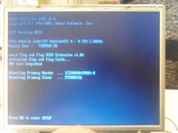
- Vendor ID? 1039, (for other boards, you can look at the second boot screen or in the device manager, in the properties of the network card.)
- device ID? 0900, (for other boards, you can look at the second boot screen or in the device manager, in the properties of the network card.)
- PCI device type? (e.g. 020000 for Ethernet):020000
Let's call the resulting file plpbt_PCI.rom. Now you need to add the resulting file to the Bios firmware. For this, we take a similar Award Bios with which Cbrom works fine. I took the firmware from Foxconn 461XP219.BIN.
By using
>cbrom198 461XP219.BIN /other 4011:0 plpbt_PCI.rom
add the bootloader to the firmware from Foxconn, after freeing up space for it in the same way as I wrote earlier. Now our bootloader has been added with the necessary headers to the firmware. It remains to transfer it from Foxconn to Asus firmware. To do this, in the HEX editor, in the 461XP219.BIN file, find the plpbt_PCI.rom module, select it from the beginning (-lh5- minus 2 bytes) to the end and copy it to a separate file. In the HEX editor, open Asus Bios a2h0213a.bin, find immediately after the last module (650lv2.08q) an empty space (FF FF FF FF FF FF FF FF FF FF FF FF FF FF FF) and immediately, without a space, after the CRC byte, insert our pulled from Foxconn firmware, plpbt_PCI.rom file. We save all the firmware and open it in BIT14.exe.
■ Award Decompression BIOS structure:
no. Item-Name Original-Size Compressed-Size Original-File-Name
───────────────────────────────────────────────────────────────────────
0 System BIOS 20000h (128K) 114C5h (69.19K) stn.bin
1 IA-32 Microcode 502Ah (20.04K) 389Eh (14.15K) cpucode.exe
2 Other(6000:0000) 86D0h (33.7K) 43E1h (16.97K) awardext.rom
3 Other(A800:0000) 6C81h (27.13K) 44B1h (17.17K) FILE1.ROM
4 Other(A000:0000) 1830h (6.05K) B58h (2.84K) AWARDEYT.ROM
5 ACPI table 3D38h (15.3K) 19DAh (6.46K) ACPITBL.BIN
6 Other(8000:0000) 1525h (5.29K) 106Eh (4.11K) ADJ_A2H.ROM
7 OEM1 CODE C000h (48K) 728Dh (28.64K) 650lv2.08q
(Silicon Integr. Sys. (SiS) SiS650/1/GL/GX,740 GUI 2D/3D Accelerator BIOS)
8 LOGO1 ROM 7400h (29K) 72DBh (28.71K) plpbt_PCI.rom
(Silicon Integr. Sys. (SiS) SiS900 10/100 Ethernet Adapter BIOS)
───────────────────────────────────────────────────────────────────────
■ Award Decompression BIOS Main CheckSums Status:
───────────────────────────────────────────────────────────────────────
no. Item-Name CheckSum Calculated-CheckSum Address Status
───────────────────────────────────────────────────────────────────────
0 System BIOS 80h 80h 114C5h Correct
1 IA-32 Microcode 0Bh 0Bh 14D64h Correct
2 Other(6000:0000) 25h 25h 19146h Correct
3 Other(A800:0000) 1Dh 1Dh 1D5F8h Correct
4 Other(A000:0000) F2h F2h 1E151h Correct
5 ACPI table 46h 46h 1FB2Ch Correct
6 Other(8000:0000) A5h A5h 20B9Bh Correct
7 OEM1 CODE 68h 68h 27E29h Correct
8 LOGO1 ROM ─── 8Bh ────── Absent
───────────────────────────────────────────────────────────────────────
In the file structure, we see the added module No. 8 as LOGO1 ROM - this is due to ID4011: 0, this does not bother us. Next, we find the dashes in the checksum and addres columns, and between the dashes the calculated CRC of module No. 8. You need to write “8B” into the firmware after the plpbt_PCI.rom module immediately after the zero byte and save the firmware. Control, open the firmware again with pom. BIT14.exe and check module #8, it should look like this:
8 LOGO1 ROM 8Ch 8Ch 27E2Bh Correct
We flash a2h0213a.bin into a flash, reboot and go to Bios Setup.
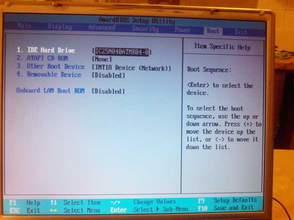
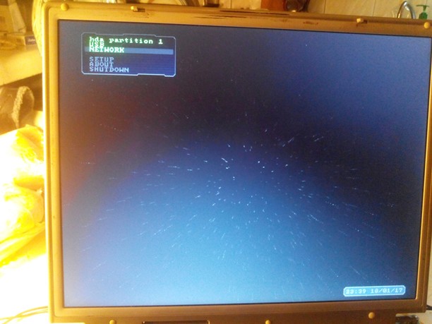
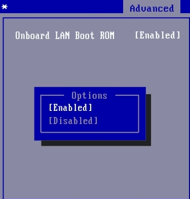
In the Boot section, in the “Onboard Lan Boot ROM” column, set Enable. In the list of boot devices, turn on “INT18 Dewice (Network)” and raise it to the very top so that INT18 Dewice is under No. 1 of the list. We reboot and, if everything is done correctly, we see the Plop menu of the bootloader.
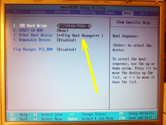
You can use. If desired, for beauty, you can change the inscriptions in Bios Setup, for example, for example, replace “Onboard Lan Boot ROM” with “Plop Boot Manager Rom”.
Addition:
From my point of view, having a modified bios and not seeing it in the bios setup is, to put it mildly, not aesthetically pleasing. Therefore, it was decided to replace the inscription “INT18 Device (Network)” and “On Board Lan Boot ROM” with something more believable, associated with the added bootloader module. Although everything done earlier is already fully functional and can be completely left as is, it is up to each individual to decide. I am for aesthetics and my choice is obvious.
We open the BIOS file in the HEX editor and find the AWARDEXT.ROM module. Next, according to the familiar scenario: select, copy and unpack it. In the unpacked form, reopen it in the HEX editor. We search for the text “INT18 Device (Network)” and write instead our inscription in Latin “** Plop Boot Manager **”, here I did not change the number of characters, I don’t know for sure what will happen if I add or remove a couple of letters, most likely it does not matter, but did not experiment. We do the same with another header that defines Boot over the network (the Plop manager is added as a network device).
After, again, the familiar procedures, we add the edited module to the “left” firmware from Award 6.0 using the already familiar CB-rum that normally works with this “left” Award. (>cbrom198 461XP219.BIN / other 6000 :0 AWARDEXT.ROM). And again in the HEX editor, as with the loader module, select AWARDEXT.ROM from the beginning (-lh5- minus 2 bytes) to the end and copy it to a separate file. In the HEX editor, open Asus Bios a2h0213a.bin and change the AWARDEXT.ROM module to the edited one. Attention here!!! The new (edited AWARDEXT) may differ in size from the original. It is necessary to control:
1.So that the module (+ CRC byte) is added without spaces and remnants of old modules, if it (the module) came out shorter in size;
2. So that the module does not overwrite the module following it with its “fost”, if it is longer ...
3.To keep the total firmware size the same (262144);
4.To keep the decompressor module and bootblock in their original places in the address space.
And if everything is fine, we continue.
Imagine purely hypothetically 🙂 that your system has stopped loading for one reason or another. There are files on the hard drive, parting with which is like the end of the world. We urgently need to do something to save them, but there is no flash drive at hand, optical disc and other emergency ambulance gadgets. For a moment, remember that at home there is a working laptop of a younger sister, previously combined with your PC in. Fast (simplified system including taskbar, start menu, windows explorer, kit useful programs, browser and more). Next, download and install the utility. We begin repair and restoration work on the PC. But from now on, in more detail.
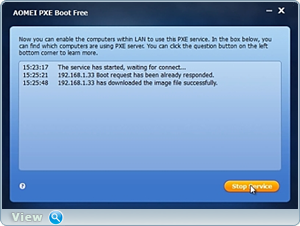
You can start repair and restoration work. I completely forgot to say. As soon as such a window appears on the server computer (sister's computer), you can click the "Stop Service" button and go about your business. Even turn off the computer. We don't need him anymore.
Other options network boot computer through an integrated network adapter(LAN Option ROM). way up desired setting:
For AMI BIOS version 2.5x/2.6x/3.31: Main -> Integrated Peripherals. For AMI BIOS version 2.5x/2.6x on motherboards ASUS boards: Main -> Advanced -> Onboard Devices Configuration. For AWARD BIOS 4.51PG: Main -> Integrated Peripherals. For Phoenix Award BIOS 6.0: Main -> Peripherals -> Onboard Device. For Phoenix Award BIOS 6.0PG: Main -> Integrated Peripherals. For Award BIOS 6.0 on ASUS motherboards: Main -> Advanced. For Phoenix Award BIOS 6.0 on ASUS motherboards: Main -> Advanced -> Onboard Devices Configuration (my case).
Identical option for LAN Option ROM:
BootROM Function
Intel 82573E Boot ROM
LAN Boot ROM
MAC LAN Boot ROM
Marvell Gigabit LAN ROM
nVidia Giga Lan Boot ROM
Onboard 1st nVidia LAN
Onboard 2nd nVidia LAN
OnBoard Giga LAN Boot ROM
OnBoard Intel LAN Boot ROM
OnBoard LAN Boot ROM
Onboard LAN Option ROM
Onboard LAN1 Boot ROM
Onboard LAN2 Boot ROM
OnBoard Marvell LAN Boot ROM
OnBoard NV LAN Boot ROM
Realtek RTL8110S Boot ROM
Warning: If you do not understand anything, do not go into the BIOS. God forbid, you will miss and cut down the network card, after which the World Wide Web will have to be searched long and hard in other Galaxies 🙂. Hi all!
Help the victim of the capitalist cataclysm. Share the post on social media networks:
What is Onboard lan boot rom?
In this article, we will consider such a fairly common BIOS option as onboard lan boot rom. It is found on many motherboards, but far from everyone knows why she needs it.
This option depends on bios versions may have slightly modified names:
- BootROM Function;
- Boot From LAN First;
- Boot to Network;
- Intel 82573E Boot ROM;
- LAN Boot ROM
- LAN Option ROM;
- MAC LAN Boot ROM
- OnBoard LAN Boot ROM;
- Onboard LAN Option ROM;
- OnBoard Marvell LAN Boot ROM;
- OnBoard NV LAN Boot ROM;
- PXE Boot to LAN;
- Realtek LAN ROM Initial.
What is Onboard lan boot rom for?
As many of you should know, the computer immediately after clicking starts looking for a boot device to start booting the system. This device is most often HDD, flash drive or disk.
Onboard lan boot rom option in bios
But thanks to the onboard lan boot rom option, booting the computer is possible without them. And it will be produced over the network from a special centralized server. This is often done in large companies, where all data, including data, is stored on a server, and workstations are loaded from it.
This greatly simplifies the process of administering such a network, where you do not need to go to each computer and rearrange the operating system on it if it fails.
Thanks to the onboard lan boot rom, this can be done remotely.
In order to boot from the network, onboard lan boot rom must be in the position Enabled(activated), and in the list of device boot order (boot) should come first.
If you do not plan to use the boot of the computer from the network, then it is better to put the onboard lan boot rom in the position " Disabled» (off).
This will speed up the boot of your computer, because it will not have to waste time searching for a download server on the network.
Other parameters identical in purpose: LAN Boot ROM, LAN option rom, Boot ROM Function.
The Onboard LAN boot ROM option is for configuring the boot parameters of a personal computer. The option has only two options - Enabled (Enabled) or Disabled (Off).
In most cases Personal Computer is loaded using the built-in system unit storage media, such as a hard drive; or removable storage media, such as an optical or floppy disk. In order for the computer to perform its functions, these drives must contain an operating system (or several operating systems). However, there may be exceptions to this rule. The fact is that many motherboards with built-in network cards can support booting operating system located not on the computer itself, but on a remote server.
This feature can be useful in many cases, for example, for computers used as workstations and terminals that do not have a hard drive, and all files necessary for the user are stored on remote file servers. Also, using a network card, remote installation of the operating system on a personal computer can be carried out. This installation method eliminates the need for removable media drives such as floppy disk drives. A similar method can be used system administrators to deploy the operating system in a short time on several network computers at once.
To implement such a boot, many BIOSes have the Onboard LAN boot ROM option or similar options. This feature allows the user to enable or disable the remote operating system boot mode using the network card built into the motherboard.
After enabling the option during computer boot BIOS motherboard transfers control to the built-in network card. Such a card usually has its own BIOS built into Read Only Memory (ROM). After control is transferred, LAN card connects to the network to find the necessary server there and download the operating system to the computer from it. If such a server is found, then the operating system is loaded, and if not, then boot control is transferred back motherboard BIOS board, which continues to search for boot devices according to the standard procedure - among the drives installed in the computer itself.
Typically, the Onboard LAN boot ROM option is located in the BIOS section where the system boot options are located. Such a section may be called, for example, Boot Settings Configuration. The Enabled option enables the function of booting the operating system over the network, and the Disabled option disables it. Also, the option may have other names, depending on the motherboard, for example:
- BootROM Function,
- Intel 82573E Boot ROM,
- Marvell Gigabit LAN ROM,
- Realtek RTL8110S Boot ROM,
Should I enable the option?
In most cases, the Onboard LAN boot ROM option is not needed by the user and it is recommended to turn it off. It may only make sense for users who are connected to local network and load the operating system from it. However, even if you do not load the operating system from the network, but leave the option enabled, then nothing bad will happen - if there is no operating system on the network, then control will be transferred to the bootloader of the built-in drive, for example, hard drive. However, keep in mind that searching for a system on the local network may take some time to load, which makes enabling the option undesirable.