This lesson provides the minimum knowledge needed to program Arduino systems in C. You can only view it and use it as a reference in the future. Those who have programmed in C on other systems can skip this article.
Again, this is the bare minimum. Description of pointers, classes, string variables, etc. will be given in later lessons. If something doesn't make sense, don't worry. There will be many examples and explanations in future lessons.
The structure of the Arduino program.
The structure of the Arduino program is quite simple and in its minimum form consists of two parts setup() and loop().
void setup()(
void loop() (
The setup() function is executed once, when the controller is powered on or reset. Usually, the initial settings of variables and registers take place in it. The function must be present in the program, even if there is nothing in it.
After setup() completes, control passes to the loop() function. It executes the commands written in its body (between curly braces) in an infinite loop. Actually, these commands perform all the algorithmic actions of the controller.
The original syntax rules of the C language.
; semicolon Expressions can contain an arbitrarily large number of spaces, line breaks. The sign of the end of the expression is the symbol "semicolon".
z = x + y
z= x
+y;
( ) curly braces define a function or expression block. For example, in the setup() and loop() functions.
/* … */ comment block be sure to close.
/* this is a comment block */
// single line comment, no need to close, valid until the end of the line.
// this is one comment line
Variables and data types.
A variable is a location in memory that stores information. The program uses variables to store intermediate calculation data. For calculations, data of different formats, different bit depths can be used, so variables in the C language have the following types.
| Data type | Bit depth, bit | Number range |
| boolean | 8 | true, false |
| char | 8 | -128 … 127 |
| unsigned char | 8 | 0 … 255 |
| byte | 8 | 0 … 255 |
| int | 16 | -32768 … 32767 |
| unsigned int | 16 | 0 … 65535 |
| word | 16 | 0 … 65535 |
| long | 32 | -2147483648 … 2147483647 |
| unsigned long | 32 | 0 … 4294967295 |
| short | 16 | -32768 … 32767 |
| float | 32 | -3.4028235+38 … 3.4028235+38 |
| double | 32 | -3.4028235+38 … 3.4028235+38 |
Data types are selected based on the required calculation accuracy, data formats, and so on. It is not necessary, for example, for a counter that counts up to 100, to choose the long type. It will work, but the operation will take more data and program memory, it will take more time.
Declaring variables.
The data type is specified, followed by the variable name.
intx; // declaration of a variable named x of type int
float-widthBox; // declaration of a variable named widthBox of type float
All variables must be declared before they are used.
A variable can be declared in any part of the program, but it depends on which blocks of the program can use it. Those. variables have scopes.
- Variables declared at the beginning of the program, before the void setup() function, are considered global and are available anywhere in the program.
- Local variables are declared within functions or blocks such as a for loop and can only be used within declared blocks. Multiple variables with the same name but different scopes are possible.
intmode; // variable is available to all functions
void setup()(
// empty block, no initial settings required
}
void loop() (
long count; // the count variable is only available in the loop() function
for (int i=0; i< 10;) // переменная i доступна только внутри цикла
{
i++;
}
}
When declaring a variable, you can set its initial value (initialize).
int x = 0; // variable x is declared with initial value 0
char d = 'a'; // variable d is declared with initial value equal to character code ”a”
When performing arithmetic operations with different data types, the data types are automatically converted. But it's better to always use an explicit conversion.
intx; // int variable
chary; // char variable
intz; // int variable
z = x + (int) y; // variable y explicitly converted to int
Arithmetic operations.
relation operations.
logical operations.
Operations on pointers.
bit operations.
| & | AND |
| | | OR |
| ^ | EXCLUSIVE OR |
| ~ | INVERSION |
| << | SHIFT LEFT |
| >> | SHIFT RIGHT |
Mixed assignment operations.
Choice of options, program management.
IF statement tests the condition in brackets and executes the subsequent expression or block in curly braces if the condition is true.
if (x == 5) // if x=5, then z=0 is executed
z=0;
if (x > 5) // if x >
( z=0; y=8; )
IF…ELSE allows you to choose between two options.
if (x > 5) // if x > 5, then block z=0, y=8 is executed;
{
z=0;
y=8;
}
{
z=0;
y=0;
}
ELSE IF- allows you to make multiple selections
if (x > 5) // if x > 5, then block z=0, y=8 is executed;
{
z=0;
y=8;
}
else if (x > 20) // if x > 20, execute this block
{
}
else // otherwise, this block is executed
{
z=0;
y=0;
}
SWITCH CASE- multiple choice. Allows you to compare a variable (in the example it is x) with several constants (in the example 5 and 10) and execute a block in which the variable is equal to the constant.
switch(x)(
case 5:
// code is executed if x = 5
break;
case 10:
// code is executed if x = 10
break;
default:
// code is executed if none of the previous values matched
break;
}
FOR loop. The construction allows you to organize cycles with a given number of iterations. The syntax looks like this:
for (action before the start of the loop;
condition for continuing the cycle;
action at the end of each iteration) (
// loop body code
An example of a loop of 100 iterations.
for (i=0; i< 100; i++) // начальное значение 0, конечное 99, шаг 1
{
sum = sum + I;
}
WHILE loop. The operator allows you to organize cycles with the construction:
while (expression)
{
// loop body code
}
The loop is executed as long as the expression in the brackets is true. An example of a loop for 10 iterations.
x = 0;
while (x< 10)
{
// loop body code
x++;
}
DO WHILE is a loop with a condition at the exit.
do
{
// loop body code
) while (expression);
The loop is executed while the expression is true.
BREAK- loop exit operator. Used to interrupt the execution of for, while, do while loops.
x = 0;
while (x< 10)
{
if (z > 20) break; // if z > 20, then exit the loop
// loop body code
x++;
}
GOTO is the unconditional jump operator.
goto label1; // switch to metka1
………………
metka1:
CONTINUE- Skip statements to the end of the loop body.
x = 0;
while (x< 10)
{
// loop body code
if (z > 20) continue; // if z > 20, then return to the beginning of the loop body
// loop body code
x++;
}
Arrays.
An array is a region of memory where multiple variables are stored sequentially.
An array is declared like this.
int ages; // array of 10 int variables
floatweight; // array of 100 float variables
When declaring, arrays can be initialized:
int ages = ( 23, 54, 34, 24, 45, 56, 23, 23, 27, 28);
Array variables are accessed like this:
x = ages; // x is assigned the value of element 5 of the array.
ages=32; // array element 9 is set to 32
Array elements are always numbered from zero.
Functions.
Functions allow you to perform the same actions with different data. The function has:
- the name by which she is called;
- arguments - data that the function uses for calculation;
- the data type returned by the function.
Describes a user-defined function outside the setup() and loop() functions.
void setup()(
// code is executed once when the program starts
}
void loop() (
// main code, runs in a loop
}
// declaration of a custom function named functionName
type functionName(type argument1, type argument1, … , type argument)
{
// function body
return();
}
An example of a function that calculates the sum of the squares of two arguments.
int sumQwadr (int x, int y)
{
return(x* x + y*y);
}
The function call goes like this:
d=2; b=3;
z= sumQwadr(d, b); // z will be the sum of the squares of the variables d and b
Functions can be built-in, custom, plug-in.
Very short, but this data should be enough to start writing C programs for Arduino systems.
The last thing I want to talk about in this lesson is how it is customary to style C programs. I think if you are reading this lesson for the first time, you should skip this section and come back to it later when you have something to style.
The main purpose of the external design of programs is to improve the readability of programs, to reduce the number of formal errors. Therefore, to achieve this goal, you can safely violate all recommendations.
Names in C language.
Names representing data types must be written in mixed case. The first letter of the name must be capitalized (uppercase).
Signal, TimeCount
Variables must be written in mixed case names, the first letter is lowercase (lower case).
Category: . You can bookmark.This blog is dedicated to this project, and here I will talk about the news of the project, and the achievements of the members of the user community of the program. The project is dedicated to creating a visual environment for programming Arduino boards, and therefore, before talking about the FLProg program, I want to make a small overview of existing programs designed to program these boards.
Arduino board programming environments can be divided into the following types:
- Upgraded Notepads
- Text Development Environments
- Graphical environments that visualize the structure of the code.
- Graphical environments that display code as graphics.
- Visual programming environments that do not use code.
Upgraded Notepads
This type includes the original Arduino-IDE programming environment, as well as many of its clones.
The design of the program for the controller in it takes place in the Processing/Wiring language, which is a dialect of the C language (rather C++). This environment is, in fact, a regular text editor with the ability to load written code into the controller
Text Development Environments
An alternative to the Arduino IDE is the development environment from the Atmel microcontroller manufacturer - AVRStudio.

Programming in it is done in pure C, and it already has a lot more features and is more like serious IDEs for "real" programming languages.
These two types of programs are designed for experienced programmers who know the language well and can create serious projects with them.
Graphical environments that visualize the structure of the code.
These are programs that, in fact, are a formatting extension for a regular text code editor. In it, the program is also written in C, but in a more convenient version. Now there are a lot of such environments, the most striking examples are Scratch, S4A, Ardublock. They are very good for learning to program in C, because they show the structure and syntax of the language very well. But for large serious projects, the program turns out to be cumbersome.

Graphical environments that display code as graphics
These are programs that hide code and replace it with graphic counterparts. They also repeat the structure of the language, form cycles, transitions, conditions. They are also very well suited for learning to build algorithms, with a subsequent transition to programming in classical languages. And they are also not suitable for building large projects due to the cumbersomeness of the resulting display. An example of such a program: MiniBlog, Algorithm Builder, Flowcode

The types of programs described above are designed for programmers or for those who decide to study classical programming. But for the manufacture of the final device, in addition to directly programming the controller, it usually requires the development of an external board binding, the development and calculation of the power section, input decoupling, and much more. Programmers often have problems with this. But electricians and electronics engineers do an excellent job with this. But among them there are few programmers who could write a program for the controller. The combination of a programmer and an electronics engineer is a rather rare case. As a result of this situation, real, completed projects based on Arduino boards (and other controllers) are few. To solve this problem, programs of the latter type are used.
Visual programming environments that do not use code.
These programs implement a principle that has been used by almost all manufacturers of industrial controllers for many years. It consists in creating programs for the controller in FBD or LAD languages. In fact, as such, they are not languages. Rather, they are graphical environments for drawing circuit or logic diagrams. Recall that processors were by no means always microprocessors, but were created on the basis of digital microcircuits. Therefore, those who are used to working with digital technology will enjoy working on them more than writing code in classical programming languages. Examples of such programs are the Horizont and FLProg projects. Programs of this type are well suited both for studying the construction of impulse and relay technology, and for creating serious projects.

And finally, the hero of this blog, the FLProg project.
Since I have been working as a process control system developer for many years, I tried to collect in the FLProg program everything that I liked the most in environments from leading manufacturers of industrial equipment (Tia-Portal, Zelio Soft, Logo Soft Comfort).
The program allows you to draw diagrams in two forms: functional diagrams (FBD) and relay diagrams (LAD).

FBD (Function Block Diagram) is a graphical programming language of the IEC 61131-3 standard. The program is formed from a list of circuits executed sequentially from top to bottom. When programming, sets of library blocks are used. A block (element) is a subroutine, function or functional block (AND, OR, NOT, triggers, timers, counters, analog signal processing blocks, mathematical operations, etc.). Each individual chain is an expression composed graphically of the individual elements. The next block is connected to the output of the block, forming a chain. Inside the chain, blocks are executed strictly in the order of their connection. The result of the circuit calculation is written to an internal variable or fed to the controller output.

Ladder Diagram (LD, LAD, RKS) - the language of ladder (ladder) logic. The syntax of the language is convenient for replacing logic circuits made on relay technology. The language is aimed at automation specialists working in industrial enterprises. Provides a clear interface to the logic of the controller, which facilitates not only the tasks of actual programming and commissioning, but also a quick troubleshooting in the equipment connected to the controller. The ladder logic program has a visual and intuitive graphical interface for electrical engineers, representing logic operations as an electrical circuit with closed and open contacts. The flow or absence of current in this circuit corresponds to the result of a logical operation (true - if current flows; false - if current does not flow). The main elements of the language are contacts, which can be figuratively likened to a pair of relay or button contacts. A pair of contacts is identified with a logical variable, and the state of this pair is identified with the value of the variable. A distinction is made between normally closed and normally open contact elements, which can be compared to normally closed and normally open pushbuttons in electrical circuits.
This programming method turned out to be very convenient for easy entry into the development of automated control systems for electrical and electronic engineers. When developing device designs, they can easily link the operation of these installations to the controller's operation algorithms.
The FLProg program built on these representations works with Arduino. Why?
The board is very convenient for the rapid development and debugging of your devices, which is important not only for radio amateurs, but is very useful, for example, in school circles and college laboratories. One advantage is that you don't need a programmer. You connect the Arduino board to the computer and download the finished program from the development environment. Currently, there is a rich selection of Arduino modules, additional modules that work with Arduino, sensors and executors.
The following versions of Arduino are currently supported by the program: Arduino Diecimila, Arduino Duemilanove, Arduino Leonardo, Arduino Lilypad, Arduino Mega 2560, Arduino Micro, Arduino Mini, Arduino Nano (ATmega168), Arduino Nano (ATmega328), Arduino Pro Mini, Arduino Pro ( ATmega168), Arduino Pro (ATmega328), Arduino UNO. In addition, the Intel Galileo gen2 board has recently appeared in the list of supported controllers. In the future, this list is also expected to be replenished, and, possibly, the addition of boards based on STM controllers.

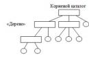
A project in the FLProg program is a set of original boards, each of which contains a complete module of the general circuit. For convenience, each board has a name and comments. Also, each board can be rolled up (to save space in the work area when work on it is finished) and deployed.
The composition of the library of elements for the FBD language at the moment.
Decor
- Inscription
- Image
- State table
- Send to UART
- Receiving from UART
- Sending variable to UART
- Receiving variable from UART
- ServoMotor
- stepmotor
- Display on HD44780 chip
- Display backlight on HD44780 I2C chip
- String addition
- String comparison
- Line length
- Substring search
- Getting a substring
- Get character from string
- Append Char to String
- Writing an element to an array
- Getting an element of an array
- Sum of array elements
- Finding an element in an array
- Uploading a file from an SD card
- Write variable to SD card
- String conversion
- -> bytes
- -> Char
- Terminal Expander 74HC595
- MAX7219 LED driver
- Decoder
- Encoder
- Reading a bit
- Recording a beat
- Matrix keyboard
- Piezo speaker
- OneWare Bus Scan
- Write to EEPROM
- Reading from EEPROM
- RessiveVariableFromCommunication
- WebServerPage
- SendVariableFromCommunication
- WebClient
- narodmon.ru
- goplusplatform.com
The composition of the library of elements for the LAD language at the moment.
Decor
- Inscription
- Image
- Contact
- Coil
- Chatter protection
- Leading edge detection
- State table
- Bistable relay
- Time relay
- Generator
- Comparison relay
- RANDOM
- Scaling
- Mathematics
- Counter
- analog switch
- Many to One Switch
- One to many switch
- Controller analog input
- Controller analog output
- Analog connector input
- Analog connector output
- speed counter
- Send to UART
- Receiving from UART
- Sending variable to UART
- Receiving variable from UART
- Servo motor
- stepper motor
- To get data
- Alarm
- Time setting
- Display on HD44780 chip
- Display backlight control unit based on HD4480 I2C chip
- Decoding block of the seven-segment indicator
- String addition
- String comparison
- Line length
- Substring search
- Getting a substring
- Get character from string
- Append Char to String
- Writing an element to an array
- Getting an element of an array
- Sum of array elements
- Finding an element in an array
- Ultrasonic Distance Meter HC-SR04
- Temperature and humidity sensor DHT11 (DHT21, DHT22)
- Temperature sensor DS18x2x
- IR Resive
- BMP-085
- BH1750 Light Meter
- Write variable to SD card
- Uploading a file from an SD card
- String conversion
- Convert Float to Integer
- -> bytes
- -> Char
- Terminal Expander 74HC595
- MAX7219 LED driver
- Encoder
- Decoder
- Reading a bit
- Recording a beat
- Matrix keyboard
- Piezo speaker
- OneWare Bus Scan
- Write to EEPROM
- Reading from EEPROM
- Block sending variable via communications
- Reception of a variable via communications
- Web server page
- web client
- Data transfer to narodmon.ru
- Remote control via RemoteXY
I will tell you more about the project in subsequent posts, and finally, a short video showing the principles of working in the program and the ability to control the board from an application on a smartphone.
You can help and transfer some funds for the development of the site
Hello! I am Alikin Alexander Sergeevich, a teacher of additional education, I lead the circles "Robotics" and "Radio Engineering" in the Central Children's and Youth Theater of Labinsk. I would like to talk a little about a simplified way to program Arduino using the ArduBloсk program.
I introduced this program into the educational process and am delighted with the result, it is in special demand among children, especially when writing simple programs or for creating some initial stage of complex programs. ArduBloсk is a graphical programming environment, i.e. all actions are performed with drawn pictures with signed actions in Russian, which greatly simplifies learning the Arduino platform. Children from the 2nd grade can easily master working with Arduino thanks to this program.
Yes, some might say that Scratch still exists and is also a very simple graphical environment for Arduino programming. But Scratch does not flash the Arduino, but only controls it using a USB cable. Arduino is dependent on the computer and cannot work autonomously. When creating your own projects, autonomy for Arduino is the main thing, especially when creating robotic devices.
Even the well-known LEGO robots, such as NXT or EV3, are no longer so interesting to our students with the advent of the ArduBloсk program in Arduino programming. Also, Arduino is much cheaper than any LEGO designers and many components can simply be taken from old consumer electronics. The ArduBloсk program will help not only beginners, but also active users of the Arduino platform in their work.
So, what is ArduBlock? As I said, this is a graphical programming environment. Almost completely translated into Russian. But in ArduBloсk, the highlight is not only this, but also the fact that the ArduBloсk program written by us is converted into Arduino IDE code. This program is built into the Arduino IDE programming environment, i.e. it is a plugin.
Below is an example of a blinking LED and a converted program in the Arduino IDE. All work with the program is very simple and any student can understand it.

As a result of working on the program, you can not only program the Arduino, but also study commands that are incomprehensible to us in the text format of the Arduino IDE, but if you are too lazy to write standard commands, you should quickly sketch out a simple program in ArduBlok with a quick mouse manipulation, and debug it in the Arduino IDE .
To install ArduBlok, you first need to download and install the Arduino IDE from the official Arduino website and understand the settings when working with the Arduino UNO board. How to do this is described on the same site or on Amperk, or look at YouTube. Well, when you figured out all this, you need to download ArduBlok from the official website, here. I do not recommend downloading the latest versions, they are very difficult for beginners, but the version from 2013-07-12 is the most important, this file is the most popular there.
Then, we rename the downloaded file to ardublock-all and in the "documents" folder. Create the following folders: Arduino > tools > ArduBlockTool > tool and in the latter we throw the downloaded and renamed file. ArduBlok works on all operating systems, even on Linux, I personally tested it on XP, Win7, Win8, all examples are for Win7. The installation of the program is the same for all systems.

Well, if it's easier, I prepared an archive on the Mail-disk 7z, unpacking which you will find 2 folders. In one, the Arduino IDE program is already working, and in the other folder, the contents must be sent to the documents folder.
In order to work in ArduBlok, you need to run the Arduino IDE. Then we go to the Tools tab and there we find the ArduBlok item, click on it - and here it is, our goal.

Now let's deal with the interface of the program. As you already understood, there are no settings in it, but there are plenty of icons for programming, and each of them carries a command in the Arduino IDE text format. There are even more icons in new versions, so it is difficult to deal with the latest version of ArduBlok and some of the icons are not translated into Russian.

In the section "Management" we will find a variety of cycles.

In the "Ports" section, we can manage the values of the ports, as well as the sound emitters, servos or ultrasonic proximity sensors connected to them.

In the "Numbers / Constants" section, we can choose digital values or create a variable, but you are unlikely to use the one below.

In the "Operators" section, we will find all the necessary comparison and calculation operators.

The Utilities section mostly uses icons over time.

"TinkerKit Bloks" is the section for purchased TinkerKit sensors. Of course, we don’t have such a set, but this does not mean that the icons will not work for other sets, on the contrary, it is very convenient for the guys to use icons such as turning on an LED or a button. These signs are used in almost all programs. But they have a peculiarity - when they are selected, there are incorrect icons indicating ports, so they must be removed and the icon from the “numbers / constants” section should be replaced at the top in the list.

"DF Robot" - this section is used if there are sensors specified in it, they are sometimes found. And our today's example is no exception, we have "Adjustable IR Switch" and "Line Sensor". The "line sensor" is different from the one in the picture, as it is from Amperka. Their actions are identical, but the sensor from Amperka is much better, since it has a sensitivity regulator.

Seeedstudio Grove - I have never used the sensors of this section, although there are only joysticks. This section has been expanded in new versions.

And the last section is "Linker Kit". The sensors presented in it did not come across to me.
I would like to show an example of a program on a robot moving along the strip. The robot is very simple, both in assembly and in acquisition, but first things first. Let's start with its acquisition and assembly.
Here is the set of parts itself, everything was purchased on the Amperka website.

- AMP-B001 Motor Shield (2 channels, 2 A) 1 890 rubles
- AMP-B017 Troyka Shield RUB 1,690
- AMP-X053 Battery compartment 3×2 AA 1 60 RUB
- AMP-B018 Line sensor digital 2 580 RUB
- ROB0049 Two-wheel platform miniQ 1 1890 RUB
- SEN0019 Infrared obstacle sensor 1 390 RUB
- FIT0032 Mount for infrared obstacle sensor 1 90 RUB
- A000066 Arduino Uno 1 1150 RUB

To begin with, we will assemble the wheeled platform and solder the wires to the engines.

Then we will install racks to mount the Arduino UNO board, which were taken from the old motherboard or other similar mounts.

Then we attach the Arduino UNO board to these racks, but we can’t fasten one bolt - the connectors get in the way. You can, of course, solder them, but it's up to you.

Next, we attach the infrared obstacle sensor to its special mount. Please note that the sensitivity control is on top, this is for ease of adjustment.


Now we install digital line sensors, here we have to look for a couple of bolts and 4 nuts for them. We install two nuts between the platform itself and the line sensor, and fix the sensors with the rest.

The next install Motor Shield or in another way you can call the motor driver. In our case, pay attention to the jumper. We will not be using a separate power supply for the motors, so it is installed in this position. The lower part is sealed with electrical tape, so that there are no accidental short circuits from the USB connector of the Arduino UNO, just in case.


Install Troyka Shield on top of Motor Shield. It is necessary for the convenience of connecting sensors. All the sensors we use are digital, so the line sensors are connected to ports 8 and 9, as they are also called pins, and the infrared obstacle sensor is connected to port 12. Be sure to note that you cannot use ports 4, 5, 6, 7 as they are used by the Motor Shield to control the motors. I even specially painted over these ports with a red marker so that the students could figure it out.

If you have already noticed, I added a black sleeve, just in case, so that the battery compartment we installed does not fly out. And finally, we fix the entire structure with an ordinary rubber band.
Battery compartment connections can be of 2 types. First wire connection to Troyka Shield. It is also possible to solder the power plug and connect it to the Arduino UNO board itself.


Here is our robot ready. Before you start programming, you will need to learn how everything works, namely:
- Motors:
Port 4 and 5 are used to control one motor, and 6 and 7 the other;
We adjust the rotation speed of the motors with PWM on ports 5 and 6;
Forward or backward by signaling ports 4 and 7.
- Sensors:
We are all digital, so they give logical signals in the form of 1 or 0;
And in order to adjust them, they have special regulators and with the help of a suitable screwdriver they can be calibrated.
Details can be found at Amperka. Why here? Because there is a lot of information on working with Arduino.
Well, we, perhaps, looked at everything superficially, studied and, of course, assembled the robot. Now it needs to be programmed, here it is - the long-awaited program!

And the program converted to Arduino IDE:
Void setup() ( pinMode(8 , INPUT); pinMode(12 , INPUT); pinMode(9 , INPUT); pinMode(4 , OUTPUT); pinMode(7 , OUTPUT); pinMode(5, OUTPUT); pinMode(6 , OUTPUT); ) void loop() ( if (digitalRead(12)) ( if (digitalRead(8)) ( if (digitalRead(9)) ( digitalWrite(4 , HIGH); analogWrite(5, 255); analogWrite( 6, 255); digitalWrite(7 , HIGH); ) else ( digitalWrite(4 , HIGH); analogWrite(5, 255); analogWrite(6, 50); digitalWrite(7 , LOW); ) ) else ( if (digitalRead (9)) ( digitalWrite(4 , LOW); analogWrite(5, 50); analogWrite(6, 255); digitalWrite(7 , HIGH); ) else ( digitalWrite(4 , HIGH); analogWrite(5, 255); analogWrite(6, 255); digitalWrite(7 , HIGH); ) ) ) else ( digitalWrite(4 , HIGH); analogWrite(5, 0); analogWrite(6, 0); digitalWrite(7 , HIGH); ) )
In conclusion, I want to say that this program is just a godsend for education, even for self-study, it will help you learn the Arduino IDE commands. The most important highlight is that with more than 50 installation icons, it starts to "fail". Yes, indeed, this is a highlight, since constant programming only on ArduBlok will not teach you how to program in the Arduino IDE. The so-called "glitch" makes it possible to think and try to remember commands for precise debugging of programs.
I wish you success.
Sergei Glushenko
Currently, the world has begun a boom in the use of microcontrollers in various homemade products and startups. Indeed, the prices of microcontrollers have fallen, and their capabilities are constantly growing. Yes, and our friends, the Chinese, have learned to make peripherals for them, and they sell it, moreover, at ridiculous prices. But with the programming of microcontrollers, everything is not so rosy ...
How it all started and how it developed
From the very moment of the appearance of microprocessors, the development of principles for working with them has been on the path of growth of abstraction. The first stage represented programming directly in machine codes. Programming was complex, time consuming and required a very specific mindset. Therefore, there were very few programmers.
But man is a lazy creature, and laziness, as you know, is the engine of progress. Invented the first level of abstraction - assembler. Writing programs just got easier and more fun. The number of programmers has increased. But still, assembler was not very different from machine codes.
Therefore, the next level of abstraction appeared. High level languages. The main purpose of these languages was the ability to explain to the machine what they want from it, in a language as close as possible to the human. This allowed people with a less specific mindset to do programming. Therefore, with the development of high-level languages, the number of programmers grew, and the number of useful programs that they created grew accordingly.
How are things now
Of course, to start working directly with the controller, some preparation is required. That is, you need a programmer, a customized environment for programming on a computer, and, of course, knowledge of a programming language. In addition, skills in working with a soldering iron, designing printed circuit boards, and knowledge in electrical and electronics are required. So the threshold for entering the field of creating your own devices on microcontrollers remains high.
In addition, such work requires a combination of skills that are rarely found together. Programmers are rarely friends with a soldering iron, and electronics engineers are not often programmers. For programmers, the problem was solved with the creation of the Arduino board, which allows you to assemble devices without the use of tools.

For electronics and electricians, things are getting worse. Until recently, in order to create their own device using a microcontroller, they had two ways. Either learn the C programming language yourself, or ask a programmer for help. Both ways are not the best. In order to become a programmer, you need a certain mindset, which is not always compatible with the experience of reading electrical circuits. A familiar programmer may not be at hand.
At the same time, there have long been programming environments adapted for an ordinary electronic engineer, or just an electrician. I mean industrial controller programming environments. PLC. They allow you to create software for controllers in languages FBD And LAD. In fact, as such, they are not languages. Rather, they are graphical environments for drawing circuit or logic diagrams.
FBD (Function Block Diagram)
- graphical programming language of the IEC 61131-3 standard. The program is formed from a list of circuits executed sequentially from top to bottom. When programming, sets of library blocks are used. A block (element) is a subroutine, function or functional block (AND, OR, NOT, triggers, timers, counters, analog signal processing blocks, mathematical operations, etc.). Each individual chain is an expression composed graphically of the individual elements. The next block is connected to the output of the block, forming a chain. Inside the chain, blocks are executed strictly in the order of their connection. The result of the circuit calculation is written to an internal variable or fed to the controller output.

Ladder Diagram (LD, LAD, RKS)
 - the language of relay (ladder) logic. The syntax of the language is convenient for replacing logic circuits made on relay technology. The language is aimed at automation engineers working in industrial plants. Provides a clear interface to the logic of the controller, which facilitates not only the tasks of actual programming and commissioning, but also a quick troubleshooting in the equipment connected to the controller. The ladder logic program has a visual and intuitive graphical interface for electrical engineers, representing logic operations as an electrical circuit with closed and open contacts. The flow or absence of current in this circuit corresponds to the result of a logical operation (true - if current flows; false - if current does not flow). The main elements of the language are contacts, which can be figuratively likened to a pair of relay or button contacts. A pair of contacts is identified with a logical variable, and the state of this pair is identified with the value of the variable. A distinction is made between normally closed and normally open contact elements, which can be compared to normally closed and normally open pushbuttons in electrical circuits.
This approach turned out to be very convenient for easy entry into the development of automated control systems for electrical and electronic engineers. Developing installation projects, they could easily link the operation of these installations to the controller operation algorithms. The maintenance of these installations on site is also better when existing maintenance personnel can easily check the operation of the ACS system and find the problem. And at the same time, there is no need to call a programmer from the Center for every trifle. And this approach paid off. To date, almost all industrial automation systems are created using such development tools.

Siemens, ABB, Schneider Electric… and almost all PLC manufacturers have such a development environment. It would seem that the ideal solution for lovers of homemade products. But, as always, there is a "but". All these programming environments are tied to industrial controllers of a certain manufacturer. And the prices for these controllers are of little inspiration. It is very rare that a family budget will allow you to purchase a controller at a price of several tens of thousands of rubles.
On the other hand, Arduino boards are ideal for do-it-yourselfers and kulibins, on which our country has always been, is and will be rich. But, again, "but". These boards are programmed in C. For most of these smart people, with very straight arms growing out of place, C is the Chinese alphabet. They can invent, draw, assemble, debug and run the most complex circuits, but If, For, Case, Void, etc. - it's not for them. Of course, you can read the instructions on the Internet, play around for a while, blink the LED using an example. But for a more serious application, a detailed study of the language is necessary. And why should they?
They are not going to be professional programmers. They have a different path. They came up with something. Yes, it's easier and more beautiful to assemble with a microcontroller, but becomes a programmer for this after spending months learning the language? Of course not. Collected in the old fashioned way, simpler, of course, but in their own area.

Based on all these calculations, the FLProg project was created. The main idea of the project is to combine the principles of industrial programming with the cheapness and convenience of Arduino. The project offers a new level of abstraction with a rather bold statement -
To program microcontrollers, it is not necessary to know programming languages!
The result is a tool that allows anyone familiar with electrical engineering and electronics to create their projects on Arduino, allowing you to create your own product using these boards.
The project consists of two parts.
The first part is the desktop application FLProg, which is a graphical programming environment for Arduino boards.
When creating a new project, you will be prompted to select the programming language in which you will create the project, and the controller on which this project will be implemented.

Here is a list of Arduino boards currently supported by the program:
|
We are expecting new additions to the family of supported boards soon. The Arduino Due is on its way, and the Intel Galileo (gen.2) board was promised to be provided by the head of the Internet of Things Laboratory at the St. Petersburg State University of Telecommunications. prof. M.A. Bonch-Bruevich. Over time, as it is acquired, it is planned to support boards based on STM controllers.
 A project in FLProg is a set of boards, each of which contains a complete general circuit module. For convenience, each board has a name and comments. Also, each board can be rolled up (to save space in the work area when work on it is finished) and deployed. A red indicator in the board name indicates that there are errors in the board layout.
The library of elements is located in the right part of the working area. Elements are transferred to the scheme by simple drag and drop. Double-clicking on an element will display information about it.
Here is a list of blocks available today.
|
Basic elements
Special Blocks triggers
Timers
Counters
Mathematics
Comparison Com port send Switch
|
Motors ServoMotor Real time clock
Displays Display on HD44780 chip Strings String addition Sensors
SD card Write variable to SD card Type conversion String conversion Extension ICs Terminal Expander 74HC595 Bit Operations Encoder Miscellaneous Matrix keyboard Write to EEPROM Communications SendVariableFromCommunication |
|
Base blocks Contact Special relays Bistable relay Algebra SIN Analog Blocks Scaling Comm Port Transfer to ComPort Motors Servo motor Real time clock To get data |
Displays Display on HD44780 chip Strings String addition Sensors Ultrasonic Distance Meter HC-SR04 SD card Write variable to SD card Type conversion String conversion Extension ICs Terminal Expander 74HC595 Bit Operations Encoder Miscellaneous Matrix keyboard Write to EEPROM Communications Block sending variable via communications |
Currently, functional blocks are being developed to work with a three-axis gyroscope, a luxometer, and other sensors and sensors. Work is also underway to organize data exchange via bluetooth, radio channel, and RS-485 interface. In future plans. development of a SCADA system for organizing the interface of systems developed in the FLProg program on a personal computer or graphic displays.
The list of peripheral equipment supported by the program is available on the project website at the link:
For some of the equipment in the section on the site there are review articles that make it easier to understand how it is used in the program.
In the upper part of the working area there is a list of tags (variables and inputs/outputs) (FBD) or installed equipment (LAD). Tags or equipment are transferred to the diagram by simple drag and drop.
After the completion of work on the project, it is compiled. After compilation, the program "Arduino 1.5.7" will automatically open with the sketch of your project loaded. In the "Arduino IDE 1.5.7" program, you will need to specify the number of the COM port to which your controller is connected, select its type, and upload the sketch to the controller. More information about the program "Arduino IDE 1.5.7" can be found on the Arduino.ru website.

Where to download FLProg?
There is a site http://flprog.ru within the framework of the project. The main task of the site is to enable users to download the latest version of the program, learn about innovations and changes.
You can download the program without registering on the site, but for registered users, the functionality of the site is noticeably expanding. Registration is very simple and only requires email confirmation. No other data is required to be entered.
Two versions are always available on the program download page: an installer and a portable version that does not require installation. If possible, I also post a much smaller update file that allows you to upgrade from a previous version.
Also on the download page, you can see a list of innovations and fixed bugs for this version and go to the archive of previous versions.

In recent years, programming and robotics circles have become extremely popular and are accessible even to elementary school students. This became possible thanks to the use of graphical programming environments, which, it should be noted, are actively used by large companies. To talk about graphical programming environments, we have selected three of the most popular of them.
Visuino is a free graphical environment that runs on Arduino-compatible Controllino industrial controllers (PLCs). It makes it possible to create complex automation systems and IoT (Internet of Things, Internet of Things) solutions, and this can be done simply by moving and connecting visual blocks. The software environment automatically generates code for industrial controllers.
So what needs to be done. Select components (modules) from the components panel and move them to the design area. Then they need to be connected and set up properties. This is done using the object inspector.
The advantages of Visuino include a large set of components for mathematical and logic functions, servos, displays, the Internet, etc.
When the PLC is programmed, the graphical environment prompts the available way to connect to the controller. It can be a serial port, Ethernet, Wi-Fi or GSM.
Finally, your project is ready: all controllers are registered, everything works. Now, by clicking on the Arduino logo located on the top panel, you will force Visuino to create codes for Arduino and open its development environment (Arduino IDE), through which you can already compile the code and download it to the PLC.
Advice. If the installed board does not match your Arduino, you can change it using the "Select Board" command.
This graphical programming environment was created in 2003 when a group of MIT Media Lab employees decided to develop a programming language that is accessible to absolutely everyone. As a result, after some time, Scratch was introduced to the public.
Most of all, perhaps, it looks like Lego. At least the principle is the same: it's an object-oriented environment in which programs are assembled from details, colorful and bright. These details can be moved, modified, made to interact in various ways. Scratch is based on blocks of commands, such as sensors, variables, movement, sound, operators, appearance, pen, control, etc. The built-in graphics editor makes it possible to draw any object. Less than five years after the creation of Scratch, the Scratch for Arduino project (abbreviated as S4A) was born, which allows you to program the Arduino PLC.
The advantages of the system include the fact that it is Russified and completely localized - anyone who wants to find a lot of data on it. In addition, work in this graphical environment is available even for elementary school students who are not yet too confident in reading.
Advice. For those new to Scratch, there is a special resource: https://scratch-ru.info.
When a person has already fully mastered Scratch, but has not yet grown up to Wiring, on which Arduino-compatible boards are programmed, it's time to advise him the ArduBloсk tool written in Java. It is especially good for those who are fond of robotics.
What is the difference? The fact is that Scratch does not know how to flash the Arduino, it only controls its PLC via USB. Thus, Arduino cannot work on its own, because it depends on the computer.
In fact, ArduBloсk is an intermediate stage between the children's Scratch and the quite professional, albeit affordable Visuino, because, like the latter, it has the ability to flash Arduino-compatible controllers.
Advice. Don't forget to install Java machine on your PC. It does not take a lot of time.
So, more graphical environments - good and different. May the Arduino be with you.
Photo: manufacturing companies, pixabay.com Are you into programming? Yes, I'm a programmer Yes, this is a very interesting thing I'm not addicted, but my child is Yes No, I'm not interested View results Loading ... Read also: Arduino: how to turn an LCD monitor into a thermometer
Mini-PC Raspberry Pi 3 Model B + can become the center of the "smart" home