Introduction
The loading indicators we'll talk about are not only an improvement appearance, but also have purely practical benefits.
This article consists of two independent parts: processor and hard drive load indicator.
Hard drive loading indicator
Before starting to create the indicator, I decided to look for the most optimal scheme. After browsing through a number of sites, I found a relatively small variety of schemes. One of the most important criteria is to get a high-quality mod for relatively little money. Most circuits use LM3914 chips, which are not that cheap. Therefore, I began to look for a level indicator chip with an output of 5-8 LEDs. The choice fell on AN6884 due to its low price and wide availability. This microcircuit has five LEDs at the output, and passes 7mA current through each.
To read the signal, two wires are used coming from motherboard, to which the hard drive indicator LED located on the front panel is connected. Instead of an LED, an optocoupler input is connected to them (see diagram). Even if you reverse the polarity, nothing will burn. The optocoupler in the diagram is necessary for electrical isolation of the circuits of the motherboard and the indicator (this is primarily necessary to protect the motherboard).
At zero load - the phototransistor inside the optocoupler is locked - while C6 is discharged through R11. When the hard drive load increases, the phototransistor is open, and C6 begins to charge through it. The voltage on C6 changes in proportion to the load level. Depending on the capacity of C6, the rate of change in the load level changes.
The voltage from C6 is removed through the divider R12, R14. Trimmer resistor R14 is used to change the sensitivity of the indicator.
You can install any LEDs at your discretion. For myself, I set the three smaller levels to green, and the two larger ones to red.
Hard drive indicator circuit
Setting up the indicator comes down to setting its sensitivity using R14.
CPU load indicator
When the hard drive indicator was already made, I began to think about an indicator for something else. The choice fell on the processor load indicator.
During the search, two options were found - through LPT and through COM.
I chose the COM port only because it was not used, unlike LPT. While searching, I found an article by Clear66, in which he talked about connecting a car tachometer to a COM port. I liked this idea most of all because there is no need to make special circuits for converting digital values into an analog signal. The PCTach program is used for control (download link is at the end of the article).
But since there was no tachometer at hand at that moment, I had to make a homemade version of the factory one. After assembly and configuration, the processor load indicator began to show more or less accurately.
But I didn’t like the increased speed of displaying the load level, which was expressed by excessive twitching of the indicator arrow when the processor load was uneven. But this was corrected by adding an additional capacitor in parallel with the microammeter.
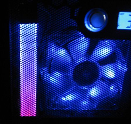
The appearance of the dial indicator did not suit me much, and I decided to look for an alternative. Ultimately, the indicator became LED, and not a scale of LEDs, but two LEDs of different glow colors directed towards each other. The load level is displayed using smooth change LED brightness.
To make the indicator, I used 4-5mm plexiglass and two LEDs: red and blue. A strip measuring 150mm by 15mm is cut out of plexiglass. After this, places for LEDs are cut out along the edges of the strip. The ends and one side of the strip should be sanded with zero-grade sandpaper to a uniform matte finish. This is necessary for uniform dispersion of light. TO back side(which is not sanded) and a strip of foil is glued to the sides of the strip to reflect the rays of the LEDs. When the strip is ready, the LEDs are glued.
Arrangement of LEDs in a strip of plexiglass
When the LEDs are already glued, electrical tape or self-adhesive film is glued to the ends of the strip. This is necessary so that the LEDs shine only in the desired part of the strip.
Blue on top symbolizes cold, i.e. low CPU load. Red below symbolizes heating, i.e. big load. The processor load is proportional to the transition of colors between each other. The wires going to the board and a 68-100 Ohm resistor are fixed at one edge of the strip using hot glue.
To smoothly change the brightness of the LEDs, a PWM signal generation circuit is used. With this control method, the brightness of the LEDs varies depending on the ratio of the time it is lit and the time it is not lit. This way better control voltage in that the brightness of the LEDs changes proportionally to the voltage.
The scheme consists of the following blocks:
voltage driver on DA1.1
Ramp generator on DA2
voltage comparison unit for DA1.2 DA1.3
The resistor divider R4, R3 sets the voltage to 1.2 volts, which is approximately equal to the minimum voltage of the sawtooth pulses DA2. Pulses are taken from the third pin of the computer's COM port. When the input level is high, capacitor C1 is charged through resistor R1 and diode D1. When the input level is low, capacitor C1 is discharged through R2. A voltage proportional to the processor load level is generated at C1. Since the amplitude of this voltage is less than the amplitude of the sawtooth pulses DA2, there is an amplifier on DA1.1 in the circuit. The maximum level of the indicator is adjusted by changing the gain using R6. The R7, C3 chain finally smoothes out the voltage ripple from the amplifier output. PWM is generated by comparing the measured voltage and sawtooth pulses.
DA1.2 generates a direct, and DA1.3 an inverted PWM signal. These two signals are then sent to LEDs, pre-amplified by switches on transistors T3, T4.
Processor indicator circuit

Execution
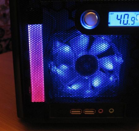
Since both indicators are located on the front panel, I made a common board for them. On one edge of the board there are two strip-shaped tracks. Two M3 nuts are soldered to these strips. In the front of the housing frame, two 3mm holes are drilled so that they correspond to the distance between the centers of the nuts on the board. Next, two M3 screws are screwed into these nuts on the board, which pass through the holes in the frame.


CPU load indicator with different load levels:


Hard drive loading indicator with different loading levels:


A long time ago, everyone desktop computers and laptops had LEDs that blinked when hard drive activity was detected. Over time, computer manufacturers decided that this was not necessary, but I disagree: if the computer suddenly does not respond, it can help to find out if there are disk accesses. If there is, it may just be a temporary delay. If not, then you will know to restart your computer.
There are other advantages to having such an indicator, of course, but computers are becoming less and less equipped with it. Fortunately, there is software solution: TrayStatus is a free utility for Windows from BinaryFortress.
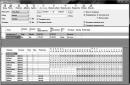
TrayStatus actually offers a number of monitoring functions, most of which reflect information about the status of the keyboard. This way you can see the icon light up when you press, say, Caps Lock or Num Lock. For our purposes, however, let's focus on the hard drive indicator.
Step 1: Download, install and run TrayStatus. ( Latest version, 2.0, includes Windows support 10.)
Step 2: Find the TrayStatus icon in the system tray, right-click on it and select "TrayStatus Settings".
Step 3: Make sure "Show Hard Drive Activity" is checked and click "OK".

Step 4: You should see the TrayStatus hard drive icon in the system tray. It will blink green when reading and red when writing. However, by default, this new icon is usually hidden in the system tray, and is only accessible by clicking the arrow, which is hardly convenient. In this case, you can delve into Windows settings, as described in the following steps.
Step 5: On Windows 10 (this process may be slightly different in more earlier versions), click Start > Settings. Then select "System", then "Notifications & Actions".

Step 6: Click the "Select the icons that appear in the taskbar" link and then scroll down until you find "TrayStatus Hard Drive." Click on the toggle switch to set it to "On". (Here you can also enable other TrayStatus indicators).
Anton Maksimov, 12/07/2012
Many modern laptops do not install indicators for pressing the Caps Lock / Num Lock keys, and in some cases they do not even install disk operation indicators. Therefore, it can be problematic to find out whether these buttons are active or whether the disk is currently working. Yes and system units often stand under the table and the user does not see whether their computer is working hard or idle. To be aware of everything that happens to your PC, you can install a small free utility called TrayStatus, which will add indicators for pressing the Caps Lock / Num Lock buttons, an indicator to the system tray work hard disk, as well as other indicators at your request.
In addition to the indicators described, TrayStatus allows you to add indicators for pressing the Ctrl, Alt, Shift and Win buttons. Frankly, I don’t quite understand why they are needed, but the disk operation indicator with Cars Lock / Num Lock is very useful in modern world. In addition to the disk performance indicator, TrayStatus can show the current read/write speed, which will allow you to understand how hard the disk is working.
Unfortunately, the utility is in English, but its ease of installation and use should not cause any problems. During operation, the utility constantly hangs in memory, therefore it takes up resources. But since this is a small utility, it takes up few resources - only 7MB of RAM, which by the standards of a modern PC is comparable to zero.
Download TrayStatus 1.2.3
Our regular readers are quite well aware of the work of specialists from the Cyber Security Research Center at Ben-Gurion University, Israel, who specialize in inventing unusual methods of hacking and stealing information from the depths of the most secure computer systems. And recently they managed to discover another potential source of information leakage, which is the familiar LED indicator that displays activity hard drive computer.
Let us remind our readers that computers that perform critical operations or contain top-secret information are in most cases protected by the so-called “air barrier”. This means that this computer is not connected to itself, nor to other computers connected to networks that have access to the Internet. This makes ordinary hacking impossible, and in order to extract information from the depths of such a computer, it is necessary to resort to very sophisticated tricks.
In their studies, the researchers found that by programming the sequence of program calls to the computer's hard drive in a certain way, it is possible to make the LED activity indicator blink at a speed of about six thousand times per second. This frequency is quite enough to transmit data at speeds of up to 4 thousand bits per second. Of course, transferring one megabyte of data at this speed will take a little over half an hour, but it will take very little time to transfer stolen messages, passwords, encryption keys and other similar information.
To use the hard drive LED as a transmitter, you will need to install it on the attacked computer special program-spy LED-it-GO, already developed by Israeli researchers. Currently, the operation of this system has been tested on computers running operating system Linux, however, researchers are confident that in exactly the same way it is possible to organize the theft of information from computers running Windows control. Positive feature this method is that all people have long been accustomed to the chaotic blinking of the computer hard drive indicator and are unlikely to notice changes in the nature of its operation. And the modulation of the LED glow with a frequency of several kilohertz is far beyond the perceptual capabilities of the human eye.
But ensuring the transmission of information through the hard drive's LED is only half the process of stealing information. The second part of the work can be taken over by a tiny spy drone equipped with a high-speed camera and photo sensors. The camera lens can be focused exclusively on the computer's LED, and then the sensitivity of the sensors will be sufficient to capture information even through the tinted glass of a closed window.
There are several options to protect against information theft in this manner. The most simple option is to turn off the hard drive LED indicator. If for some reason this cannot be done, then you can position the protected computer so that its LEDs are not visible from any window in the room. And another, more complex option is to use a special program that accesses the hard drive at random intervals, this, in turn, will create insurmountable interference for any other program trying to transmit information through the hard drive's LED.
And, as a last resort, Israeli researchers advise simply covering the LED indicator with a piece of opaque tape. This method is a clear demonstration of how common and simple materials, such as a piece of ordinary electrical tape, can effectively counteract the most sophisticated and modern spy technologies.