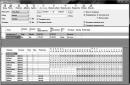
Explanation of the values of the firmware fields marked in color:
Identifier; the last three letters are the region: CHN - China, KOR - Korea, EXP - all other countries. We put EXP, accordingly. |
Cartridge capacity; values 01...09 correspond to 1...9 thousand copies, 0A - 10 thousand; the optimal value corresponding to the performance characteristics of the cartridge is 3-5 thousand copies: no matter how much you write, it will still be blocked after 5 thousand copies, the only benefit is that it will not “scream” about the end of the toner. |
Cartridge serial number; valid cell values are 30-39. The first six characters are the date in DDMMYY format. The number must be changed when updating the firmware; possible options: Add one to the number; “Eternal firmware” differs from the original factory firmware in one single byte: in the 30th line, 9F is written in the last cell, which in decimal code is read as a “dot” instead of the last digit of the serial number. In the example given, the serial number looks like 08012535359 , instead of a byte 39 (9) in this case, to make the firmware eternal you need to specify 9F, then the serial number will look like this 0801253535. , and in the printed report as: 0801253535 $ . |
Installation label; V new firmware this entry is missing, so the printer thinks it has a new cartridge and increments the toner change counter. The printer itself creates this record when installing the cartridge. It is advisable to reset. |
Page counters- if converted to decimal code, then this will be the number of printed pages. Reset. |
Toner counter- reset. |
Drum counter- reset. |
Toner Out Label; values: 00 is the norm, it should be set when flashing the firmware, i.e. reset the "Toner Out" mark. 01 - low toner - in this case the printer also works, but it will complain about “toner low”, you should not use it. 02 - no toner - everything is clear here. |
It is quite possible that such manipulations to “perpetuate” the firmware can be done on devices PE220, ML2150, Phaser 3450. It’s worth a try, in the end they won’t let you down :).
Several clarifications can be given regarding the operation of the cartridge with “eternal firmware”:
A device working with a cartridge with “eternal firmware” will not show the “toner low” and “no toner” messages on the display, and the lines “CRU pages printed” and “Number of toner replacements” will not work in the printed report. The overall page count and the number of pages scanned on the flatbed continue to work, which is quite acceptable.
When installing another cartridge with the “correct” firmware into the device, the device continues to work as with a regular cartridge, i.e. There is no abnormal impact on the device from the use of a cartridge with eternal firmware.
Remember, the program does not change the serial number of the chip and does not flash the full firmware of the chip. Therefore, the chip does not move beyond what it previously printed and it is better to use the flashed chip in a new printer.
List of printers available for flashing chips -
Xerox WorkCentre 3210.
Xerox WorkCentre 3220.
Xerox Phaser 3140.
Samsung SCX-3200.
Samsung SCX-3217.
Samsung SCX-4223F.
Samsung SCX-4300.
Samsung SCX-4600.
Samsung SCX-4623.
Samsung SCX-4824.
Samsung SCX-4828.
Samsung CLP-310/315.
Samsung CLX-3170/3171.
Samsung ML-2855.
Samsung ML-1640/1641/1645/2240/2241/2245.
Samsung ML-1910/1915/2525/2580/SP-650.
Samsung ML-1660/1665.
Standard programmer with 2 shortcuts - link
If it’s difficult with com-ports, then you can suggest a universal programmer via USB - link
The program is not mine. There is no need to say thank you.
Program for flashing chips based on 921 chips S3CC921Resetter- download .
A little theory for those who like to know everything to the end
Chip programmer S3CC921
Article by Andrey Lutov posted in the public domain
About the chip S 3 CC 921.
The impossibility of flashing the notorious Samsung chips with S3CC921 crypto-protection, and indeed their absence separately from branded cartridges, made refilling printers and MFPs where they are used impossible. Over the course of a year, we quite successfully “fought” such printers by replacing them once firmware of the printer itself to a modified one that allows the printer work without chip. But the manufacturer responded by blocking access to its firmware, and you can’t “get” the firmware from any model, so the problem of refilling cartridges for new Samsung printers remains relevant. The PS3CC921.EXE program allows you to read and write these chips with some restrictions. This is a test version of the programmer. For now, the programmer can only work with one version of the chip out of 4 possible and records only part of what is read. The limitations of the program are related to my lack of any information at all on this chip, and therefore everything stated in the following was obtained and continues to be obtained exclusively by experimental means. Nevertheless, even in this form the program can be useful.
Iron.
To run the program you need an I2C programmer for COM or LPT port, as well as a computer that has at least one " real" serial or parallel port. The program accesses them using its driver I2CDRV.SYS, so USB emulators these ports will not work. The parameters of all parallel and serial ports are taken from the registry, and then the ports are scanned for a connected programmer.
Although, according to reviews, the chip also works from a 5-volt power supply, just in case, I supplied power to it from USB through a 3.3-volt 78ls33 stabilizer. At 3.3 volts, I also attached pull-up resistors along the SDA and SCL buses.
Program.
The programmer is a console program. If run without parameters, it reads the chip and writes the contents to the 384 byte file RS3CC921.BIN in the current folder. When launched with a filename in command line the program reads uh That file writes the contents to the chip. Only files 384 bytes long are accepted.
Edit the resulting binary s th file can be used in any HEX editor, for example, FlexHex is suitable,WinHex.
As I understand it, the memory of the microcircuit consists of 2 blocks. The first block is 256 bytes in size and is located in the file at addresses 0x 00 –0x FF (hex ). This block is read and written by the programmer without problems, and is where most of the printer's counters are located. I note that memory area 0xC 0 –0x FF printer ami not used, and in different s chips contains different data. To prevent this information from being overwritten, I blocked writing to this area in this version of the program; data at these addresses in the file is ignored when writing. The second block is located in the file at addresses 0x 100 –0x 17F. It is readable normally, but for now it is available as one-time programmable. This means that a single write is possible only to memory cells that contain the number 0xFF. This block contains mainly constants: CRUM number, cartridge capacity and type, release date, etc. This area also contains several important one-time programmable data. This is the Exhaust toner flag (0x 14C) , toner ignore flag “Clear toner” (0x 14D), 16 byte field “Progress Bar” (0x 160- 0x 16 F). The flags are initially equal to 0x FF, and when the flags are activated, the printer writes the number “01”. Progress Bar field » in the new cartridge contains 10 bytes 0xFF. As the CRUM page counter increases, the printer fills this field from left to right with 0xA 5 bytes. If you divide the number of 0xA 5 bytes by the total number of bytes (16) and multiply by 100%, you get the percentage of toner used, calculated based on the number of pages printed. The printer periodically checks the Progress Bar ", and, if necessary, a page counter CRUM is adjusted based on this field.
While this memory is available as one-time programmable, I suggest fields on the new cartridge (Exhaust toner - 0x 14c) and "Progress Bar" (0x 160 - 0x 16 F), if they are in specific model printer, fill with zero bytes.
Usage of s3cc921 memory in various printers.
In 46xx series printer chips, you need to reset the memory area 0x 00 –0xB Toner amount at offset 0x 1 F, reset the 0xFF bytes of the Progress Bar and 0xFF bytes of the Exhaust toner field. If the Exhaust toner field is already equal to 0x01, then the chip in these printers most likely will no longer work. But these chips can, for example, be used in 1910, 2525 series printers, where this field is not used.
In printer chips 482x and 2855 series (and in XEROX 3210/3220) you also need to reset the memory area 0x 00 –0xB F, write the number 0x64 (=100% - Toner amount / toner balance) at offset 0x 1 F, reset the 0xFF byte of the Exhaust toner field. In the firmware of this series of printers, including version 41 482x, this moment The Progress Bar field is not used. But you can reset it to zero - this should not affect the operation of the printer.
In printer chips 191x, 252x series (and in XEROX 3140/3155), you need to reset the memory area 0x 00 –0xB F, reset the 0xFF bytes of the Progress Bar. The Toner amount and Exhaust toner fields are not currently used in these printers.
Resetting 164x, 224x series chips is similar to 191x. I will only note that only latest firmware use Progress Bar. That is, a chip that ends in this field can be used in printers with older firmware versions
In 4300 printers everything is simple - you need to reset the memory area 0x 00 –0xB F and that’s it.
I don’t yet have reliable information on other printers, but I think that the detailed memory cards provided will allow you to reset the firmware of these printers as well.
- < Назад
- Forward >
It’s common for the first cartridge (factory) to print 1000 copies and the message “No toner” appears. After refilling the cartridge with a new portion of toner, this message still did not disappear, the printer printed perfectly and persistently displays the message “No toner”, plus in my model the fax does not work because of this (for information, in the service menu, the NEW option CARTRIDGE didn't change anything). This means you need to reflash the printer cartridge chip.
However, this technique suits many Xerox printers and Samsung, I had the opportunity to try this out on the XEROX PE220 MFP
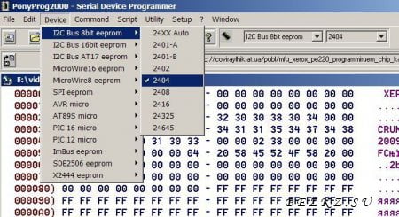
For programming you need the PonyProg2000 program and adapter:
Resistance is not critical 1kOhm-10kOhm
My XEROX PE220 chip looks like this:


Programming:
1. Connect the chip board to the programmer (PC9 connector)
2. Insert the programmer into COM1 (COM2) of the switched off computer
3. Turn on the computer, launch PonyProg2000
4. Set up PonyProg2000:
Menu "Settings - Equipment settings..."

5. Be sure to check and calibrate - it should be "Test Ok!"

6. Set the chip type:
Now let's look at the chip (byte by byte):
00-06 and 58-5E - manufacturer identifier, best not to touch.
20 - the number of thousand that the cartridge is designed for (it seems that increasing this value to a maximum of 8K, but the MFP may stop copying when the counter reaches 5K). Standard value 03. У starter cartridge resource 1K.
35-3F - change any byte (values 30-39)
40-47 - always Installed (installs itself).
78 - indication - 00 - no messages, 01 - low toner, 02 - no toner.
In short, when flashing the firmware you need to change the serial number and fill cells 40-57, 60-63, 80-83, 78 with zeros.
That's about it...
There are two firmware 01 in the archive, this was merged from the new cartridge chip.
02s, this is a working one from a printer that has gone through the entire process described in the article
8. Write the firmware to the chip. Close the program and turn off the computer. We remove (unsolder) the chip board from (from) the programmer (connector) and install it in the refilled cartridge.
That's all! Once you do it once, you realize it's all very simple.
Tested in use.
Now important notes:
1) these are not my developments, I just summarized the material. All of the above is IMHO and personal experience.
2) - you act at your own peril and risk.
3) keep in mind that resetting the drum counter does not guarantee you against all other troubles, so as soon as possible, take the copier to a service company so that they can remove the waste and make the necessary cleaning and adjustments.
Also for reference - Entering service mode:
Through service menu: to enter the service menu 4216/PE16, type on the keyboard: - [#] - - , After entering the service menu, the inscription TECH will appear; Using the [Left Arrow] - [Right Arrow] keys, find the entry "New cartridge", select "Yes". After you have completed the necessary operations (MENU-># 1934) and you are in the main menu, turn off and turn on the MFP. You just have to press quickly.
To exit service mode You can press the [Reset] button twice or simply turn the machine off and on.
4) warning for inexperienced users: NEVER use any other diagnostic codes or procedures, because this may lead to unpredictable consequences.
You cannot download files from our server cartridge eproom files
There are a sufficient number of stand-alone programmers adapted for the firmware of cartridge chips. But they all have one significant drawback: they are too difficult to manufacture by a non-specialist and at one stage require a stationary programmer. Recently, on the forum, one of the specialists posted his version of a standalone programmer. The version is based on the popular, inexpensive and accessible electronic designer Arduino. As part of this article, I will try to write instructions on how to independently assemble a programmer for ordinary users, including enthusiastic schoolchildren. Assembling a programmer is another useful and inexpensive opportunity for children and adults to immerse themselves in the magical world of electronics, without even having basic knowledge in circuit design, programming and radio electronics. List of Ricoh chips flashed by the programmer: SP150/ SP220/ SP325/ SP377 /SP311 /SP100 /SP111 /SP3500 /SP250 /SP252 /SP220 /SP310 /SP3600 /SP6430 /SG41 / SP300. As you can see, the list of supported devices is very wide. And it is not final.
For convenience, I'll start by describing the components themselves and how to work with them. So, for work we need three main elements: the “heart” of the Arduino UNO programmer itself, an lcd keypad shield and a card reader.
Arduino UNO - the heart of the programmer
There are many varieties of Arduino. For example, pro min, nano, UNO, Mega, LEONARDO. In this article, I specifically focused on the Arduino UNO version, since it is with this version that it will be easiest for a beginner to start working: upload the firmware, supply power, connect the display and keyboard. Of all the existing varieties of UNO boards, I used a Chinese clone costing 450 rubles (the original board costs from 2000 rubles).
Arduino UNO is specially designed to instantly interact with specially designed expansion modules called “Shield”. Visually it looks like a multi-layer sandwich.
Lcd keypad shield

This expansion board will be used for our programmer. The board is an LCD display with a built-in resistive keyboard and a trim resistor for adjusting the display contrast. The programmer uses a non-original board that costs 210 rubles. The keyboard contains 6 buttons; for our programmer only 4 will be used. Try to purchase the Lcd keypad shield exactly as in the photo. The operating principle of the keyboard is based on the difference in resistor resistance and other versions of this shield may contain other resistor values.
MicroSD card reader

In essence, this expansion card is a regular card reader for MicroSD cards with SPI interface. There are two types of card readers. For our programmer A card reader with a logical level converter is required, this is the version that supports a supply voltage of 5V. The cost of this module is about 60 rubles.
Programmer assembly

Trying to adapt the programmer for beginners, I tried to avoid using a soldering iron as much as possible. As practice has shown, such a programmer, due to a significant number of wires and unreliable contacts, worked extremely unstable. By the way, I tried to implement this version of the programmer on the basis of Arduino NANO, but it didn’t look much like a working version of the programmer, as you can see in the photo on the left, there’s just a huge bunch of wires, and connecting the LCD display pins is still a quest.
Therefore, for a truly reliable and stable programmer, you will still have to work a little with a soldering iron. If you don’t have a soldering iron and don’t know how to solder, then contact a skilled friend or a specialist. The entire assembly of the programmer takes no more than 5 minutes until it is fully operational. Here's a short video I took on mobile phone for assembling the programmer.
Connect MicroSD card reader

I connected the card reader using colored wires specially purchased for this in the store. I cut and stripped one end of the wire, and left the other as is. The wires themselves are inexpensive - about 70 rubles for 40 pieces, 10 cm long. Correctly, these wires are called “ Connecting wires Female - Female 40 pcs multi-colored 10 cm “. Colored wires will help you make the connection as quickly and correctly as possible, so I would recommend purchasing them for assembling the programmer, and the remaining wires can be used in other projects.
All wires will be soldered to the Lcd keypad shield. All unoccupied pins of ArduinoUNO when installing the Lcd keypad shield are duplicated directly on the expansion board itself. A total of 6 wires will not be connected according to the diagram below. Attention, the VCC (red wire) and GND (black) pins should not be confused when soldering. Essentially this is the power supply for the MicroSD card reader, VCC is a plus, and GND is a minus. If these pins are mixed up, it will lead to burnout of the electronics. If you mixed up other wires, it’s okay, just re-solder them. When turned on, the programmer checks the connection of the MicroSD card reader. If all wires are connected correctly and a working card is installed in the card reader MicroSD, then the display will show “ Test SD card success:-)”

Chip connection

There are quite a large number of varieties of chips, and for ease of connection to the chips we will use universal alligator clips. As you can see in the picture on the left, only four wires are used to connect the chip. Power supply to the chip VCC and GND, as well as directly two bidirectional communication lines DATA (Serial Data) and SCL (Serial Clock). Power is taken from the same pins as the power supply for the card reader. The wires going to the chip will break due to constant use, so try to buy ready-made wires with alligator clips. These wires have thicker and at the same time soft insulation, which increases their service life. If the firmware of chips is carried out regularly, then it is better to use an adapter to connect to the chip; I will write more about this in a separate paragraph of the article.
Completing the programmer assembly.

At this point, the actual assembly of the programmer can be considered complete. All that remains is to simply connect the Arduino UNO and Lcd keypad shield. As you can see, all wires are soldered to the Lcd keypad shield, and the Arduino UNO can be disconnected if necessary and used in other projects.
Part two - installing software into the programmer.
This part is the simplest. Fill program code in arduino uno is produced using USB cable. For this purpose, UNO has a built-in reliable USB-to-Serial converter on the ch340g chip. When connecting UNO to a computer, drivers are installed automatically. After installing the driver, a virtual COM port appears through which the Aduino and computer communicate. If you have an old one installed on your computer operating system, That .
To upload the firmware to the programmer you will need to do the following:
- Download a program for working with Arduino. (archive needs to be unpacked)
- Connect a specialized library for working with EEPROM,
- Download the programmer code (sketch). . (archive needs to be unpacked)
- It will also be necessary (more on this a little later at the end of the article) (the archive needs to be unpacked)

1) Launch the program. After downloading the arduino-1.8.4-windows.zip archive and unpacking it, run the arduino.exe file. During the process, the program will ask for a number of permissions - agree, since the program will create folders in the “My Documents” section for storing programs and libraries.
2) We connect a specialized library. Having launched the program, go to the “Sketch” menu, then select “Connect library” and click “Connect ZIP library”. Next, you need to select the previously downloaded archive Eeprom24C04_08_16-master.zip (this archive is downloaded in packed form!) and click “Select”. The library will automatically download where needed (in the libraries folder in the my documents section).
3) Setting up the program. Go to the “Tools” menu, then the “board” submenu and specify the board type “Genuino Uno”. Now connect the Arduino UNO to the computer, the drivers will be automatically installed during the process, if this does not happen, then start installing the drivers from the previously downloaded “CH341SER.zip” archive. After installing the drivers, the computer will automatically create a virtual COM port.  As a rule, this is any COM port with a serial number starting with the number 3 and onwards. The number will be different for each board, which allows you to connect several boards at once. Again, go to the “Tools” menu, then to the “Port” submenu and select the installed port, in my case it is port with serial number 5.
4) Fill the sketch into the board. Now click the “File” menu, select “Open” and open the unpacked file “programming_portable_I2C_EEPROM_v4.4_uno.ino.” Next, you need to press the download key on the main panel (arrow to the right) or select the “Download” item in the “Sketch” menu
The cartridge chip is a small flash card into which all information about the operation of this cartridge is recorded.
For example, the chip contains information about the type of cartridge, the date of its manufacture and serial number. During operation of the printer or MFP, the Additional Information about the date of its installation in the device, the current counter of prints made by the cartridge, and other technical data. When the cartridge's fingerprint counter reaches a certain value, the cartridge chip receives information that the cartridge is empty. Then the device warns the user that the cartridge is empty and needs to be replaced. Depending on the brand of printer or MFP, the equipment either continues to work with such a warning or stops.
In this case, there are several options:
1. Do not change the cartridge chip
If you have Canon or HP equipment, the chip in your empty cartridge does not block the operation of the printer or MFP, but only constantly signals that the cartridge is empty. In this case, when refilling the cartridge, you can not change it, and ignore warnings about an empty cartridge.
2. Reprogram the chip.
In Samsung and Xerox printers, the cartridge chip often blocks the operation of the printer after the cartridge becomes empty. In order for the refilled cartridge to start working, the chip is reprogrammed. This can be done in our workshops. You can also find out about the possibility of reprogramming (zeroing) the chip of your cartridge .
3. Replace the chip
If the chip cannot be reprogrammed, then it is either changed every time it is refilled, or the printer/MFP is reflashed once. You can find out about the need change the chip when refueling in our in the notes column.
4. Reflash the printer
This change software The printer will allow it to function with cartridges that do not have a chip. This is a one-time operation. You can find out more about reflashing the printer and its cost .