Development various devices based on microcontrollers is an activity worthy of a real computer geek. Undoubtedly, a useful feature of any gadget will be a USB interface for connecting to a computer. But what if the AVR chip does not provide hardware support for USB?
V-USB: size matters
When developing your own gadget, the problem of connecting it to a computer often arises. I must say that LPT and COM ports are now exotic on motherboards PCs, not to mention laptops, for which these interfaces disappeared a long time ago. Therefore modern computers There are practically no alternatives to the USB interface.
If the chip's resources are used one hundred percent, then it is better to immediately look towards devices with hardware support for the universal serial bus (such microcontrollers are present in the line of any manufacturer). In other cases, you can use software USB.
For Atmel microcontrollers there is a wonderful V-USB project that offers a software implementation of low-speed USB devices 1.1. The V-USB code will work on any AVR device that has at least 2KB of Flash memory and 128 bytes of RAM, with clock frequency 12; 12.8; 15; 16; 16.8 or 20 MHz.
The product can be used both under the open source GPL license and on a commercial basis. In order to develop your own USB devices, you usually also need to buy some sort of license. But the guys from V-USB took care of this too, purchasing a pair of Vendor ID - Product ID and allowing anyone to use them.
The hardware for connecting the USB bus to the microcontroller is very simple. If the device does not consume too much, then it can be powered directly from the bus (it is considered that the power line USB computer and is capable of delivering current up to 500 mA). Since the information lines (D+ and D–) use a signal level of 3.6 V, in addition to current limiting resistors, zener diodes are needed to match the 5 V logic of the chip. To indicate the type of connection, you need to “pull up” the supply voltage through a 1.5 kOhm resistance to line D–.
An alternative option for pairing via USB is to reduce the controller supply voltage using an appropriate stabilization chip or simply a pair of diodes. The latest diagram can be found on the V-USB project website.
USBtiny programmer
There are many different programmers for AVR microcontrollers. USBtiny is mentioned here in part because it contains a software implementation of USB similar to V-USB. The circuit of this programmer is simple: version 2 contains two microcircuits, and the first version contains only one (the ATtiny2313 chip itself). Thanks to detailed description on the website and with simple components, the device is easy to make even for a beginner. USBtiny is compatible with the popular avrdude program used for programming AVR microcontrollers.

The only problem is uploading the firmware into the programmer chip - for this you need... a programmer. If you have a computer with an LPT port, then you can make one of the options FBPRG aka “five wires”, which is
Preparing the sled
The software tools required to implement the simplest firmware for a USB gadget are extremely ascetic: the gcc-avr compiler, the avr-libc library, the avrdude programmer and the binutils set for AVR. On Debian/Ubuntu, everything you need is installed with one command:
$ sudo apt-get install avrdude binutils-avr gcc-avr avr-libc 
On the vast expanses of the Internet it is not difficult to find very detailed guide via V-USB and libusb (in English). According to the manual, to add USB support to the project you will need the usbdrv folder from the archive with latest version V-USB. At the root of this folder there is a configuration template usbconfig-prototype.h. You need to make a copy of this file, calling it usbconfig.h. Next, fix usbconfig.h by specifying the port (D), the lines of which will be used for I/O, the line numbers D+ (2) and D– (3), as well as the frequency (12 MHz) at which the chip operates (ATtiny2313 ):
#define USB_CFG_IOPORTNAME D #define USB_CFG_DMINUS_BIT 3 #define USB_CFG_DPLUS_BIT 2 #define USB_CFG_CLOCK_KHZ 12000
To use a V-USB license for a device, you do not need to change the manufacturer and device numeric IDs. But you can choose symbolic names to your liking (they will allow you to distinguish several V-USB-based devices connected to the same computer):
#define USB_CFG_VENDOR_ID 0xc0, 0x16 #define USB_CFG_DEVICE_ID 0xdc, 0x05 #define USB_CFG_VENDOR_NAME "n","e","t","s","4","g","e","e","k" ,"s",".","c","o","m" #define USB_CFG_VENDOR_NAME_LEN 14 #define USB_CFG_DEVICE_NAME "U","S","B","e","x","a" ,"m","p","l","e" #define USB_CFG_DEVICE_NAME_LEN 10
Various gadgets
Do you have an idea for any device? Don’t rush to solder and code, but look, maybe someone has already done something similar. If you can’t use ready-made diagrams and sources, then at least you won’t have to start everything from scratch.
For example, the V-USB project, thanks to its licensing policy, has accumulated a decent base of ready-made (including freely distributed) solutions. Here you can find various implementations of keyboards, USB adapters for joysticks, gamepads (including rare ones, for example SNES/NES, Nintendo 64, ZX Spectrum joystick, Sony PlayStation 1/2) and the like. DMX adapters, virtual COM and UART ports, i2c, Servo, DCF77, IR wireless interfaces - everything that will help you connect more new devices to your PC. Loggers, platforms for probes and sensors, adapters for LCD displays, programmers and loaders can also be useful in the household.
The program for the chip is elementary!
When interacting via a USB bus, the computer is the main device that periodically sends control request messages. The controller, accordingly, is a slave and must respond to requests. The control message format is determined by the usbRequest_t structure from the usbdrv.h file:
Typedef struct usbRequest ( uchar bmRequestType; uchar bRequest; usbWord_t wValue; usbWord_t wIndex; usbWord_t wLength; ) usbRequest_t;
Let's create a file main.c at the same level as the usbdrv folder and describe the necessary header files, definitions and variables in it:
#include
In main.c we will override the usbFunctionSetup function, which is called automatically when a new request is received:
USB_PUBLIC uchar usbFunctionSetup(uchar data) ( usbRequest_t *rq = (void *)data; switch(rq->bRequest) ( case DATA_OUT: // Process the command to send data usbMsgPtr = replyBuf; // Specify the buffer return sizeof(replyBuf); / / Return the buffer size case DATA_IN: // Processing the data receiving command dataLength = (uchar)rq->wLength.word; // Get the length dataReceived = 0; // There will be many calls to usbFunctionWrite if(dataLength > sizeof(replyBuf)) // Checking for overflow dataLength = sizeof(replyBuf); return USB_NO_MSG; // Return 255 ) return 0; )
As you can see from the listing, the easiest way to send data to a computer is to set usbFunctionSetup to the value of the usbMsgPtr pointer to the RAM buffer (replyBuf) where the data is located, and then return its length. The buffer size should not exceed 254 bytes. For the ATtiny2313 with its 128 bytes of RAM, this is enough. For more functional devices, there is a second way - overriding the usbFunctionRead function.
To get the data, first, you need to use the usbFunctionSetup function to extract the message length from the wLength field of the request and store it in the dataLength global variable. Secondly, in main.c you need to override the usbFunctionWrite function, which is designed to process the received data and is called automatically (and obviously several times) if usbFunctionSetup returns the value USB_NO_MSG (255):
USB_PUBLIC uchar usbFunctionWrite(uchar *data, uchar len) ( uchar i; // Save the received portion of data to a buffer for(i = 0; dataReceived< dataLength && i < len; i++, dataReceived++) replyBuf = data[i]; return (dataReceived == dataLength); }
Actually, the usbFunctionWrite function fills the replyBuf buffer with the received data.
By the way, for this method to work, you need to make changes to usbconfig.h:
#define USB_CFG_IMPLEMENT_FN_WRITE 1
Well, the last function of the firmware is main:
Int main() ( usbInit(); // Initialize USB usbDeviceConnect(); // Connect the device sei(); // Enable interrupts // Wait for control messages in an infinite loop while(1) usbPoll(); return 0; )
Let's use USART/UART
A good alternative to software/hardware USB is to use the popular USART/UART interface in the chip with a third-party converter of this protocol to USB, which can be made, for example, based on the FT232RL chip.
Libusb: neither clothed nor naked
You may ask: will you have to write a driver for the computer operating system in order to connect a USB device? If you use libusb, you can do without implementing a full-fledged kernel module. Libusb is an open source library that allows you to quickly program, firstly, searching for a device on the bus, and secondly, exchanging data with it.
Under Linux, the library and the necessary header files can be obtained from the source codes. It's better to use the standard repository of your distribution. For Debian/Ubuntu, for example, like this:
$ sudo apt-get install libusb-dev
There is also a libusb port for Windows - libusb-win32. Contrary to the name of the project, 64-bit operating systems from Microsoft are also supported (starting from version 1.2.0.0).
But libusb is a separate topic of discussion. I think you are familiar with PC programming and can figure it out on your own. So I'll be brief. Create a file usbtest.c and start filling it with content. First the necessary header files and definitions:
#include
The usbOpenDevice function to initialize the device:
Usb_init(); // Initialize USB usb_find_busses(); // Find buses usb_find_devices(); // Find devices // Enumerate all buses for(bus=usb_get_busses(); bus; bus=bus->next) ( // Enumerate all devices on the bus for(dev=bus->devices; dev; dev=dev-> next) ( // If the vendor and product IDs do not match... if(dev->descriptor.idVendor != vendor || dev->descriptor.idProduct != product) continue; // ...skip this iteration // Try to get a device handle if(!(handle = usb_open(dev))) ( fprintf(stderr, "%s\n", usb_strerror()); continue; ) return handle; // Return handle ) ) // Device not found return NULL;
As you can see, the usbOpenDevice parameters are the numeric identifiers of the manufacturer and device. If the device is present on the bus, its descriptor is returned. If there are several devices on V-USB, you will have to add a check for the symbolic names of the vendor and product.
And the main function of the usbtest console utility:
Int main(int argc, char **argv) ( // Device descriptor usb_dev_handle *handle = NULL; int nBytes = 0; char buffer; // Looking for the device handle = usbOpenDevice(0x16C0, 0x05DC); if(handle == NULL) ( fprintf(stderr, "Could not find USB device!\n"); exit(1); ) // Argument out - get data from the chip if(strcmp(argv, "out") == 0) ( nBytes = usb_control_msg (handle, USB_TYPE_VENDOR | USB_RECIP_DEVICE | USB_ENDPOINT_IN, DATA_OUT, 0, 0, (char *)buffer, sizeof(buffer), 5000); printf("Got %d bytes: %s\n", nBytes, buffer); // Argument in - send string (next argument) ) else if(strcmp(argv, "in") == 0 && argc > 2) ( nBytes = usb_control_msg(handle, USB_TYPE_VENDOR | USB_RECIP_DEVICE | USB_ENDPOINT_OUT, DATA_IN, 0, 0, argv, strlen(argv)+1, 5000); ) if(nBytes< 0) fprintf(stderr, "%s\n", usb_strerror()); usb_close(handle); // Закрыть дескриптор return 0; }
The usb_control_msg function, which is declared in the usb.h include file, rules the roost here. It has a bunch of parameters and actually creates those control messages, the processing of which is implemented in the microcontroller firmware.
Proteus is resting
Everyone's favorite electrical circuit simulator, Proteus ISIS, is useless when developing software-based USB devices. Its USB emulator only supports chips with Universal Serial Bus hardware support (such as AT90USB646 or AT90USB1286).
We assemble, flash, test
Below is a small but very useful Makefile, with which you can easily get the firmware for the chip - main.hex and the usbtest utility binary using the make command from main.c and usbtest.c:
CC = avr-gcc OBJCOPY = avr-objcopy CFLAGS = -Wall -Os -Iusbdrv -mmcu=attiny2313 OBJFLAGS = -j .text -j .data -O ihex OBJECTS = usbdrv/usbdrv.o usbdrv/oddebug.o usbdrv/usbdrvasm .o main.o CMDLINE = usbtest # Goal: collect everything all: main.hex $(CMDLINE) # Build a utility for the computer $(CMDLINE): usbtest.c gcc -I ./libusb/include -L ./libusb/lib /gcc -O -Wall usbtest.c -o usbtest -lusb # Clear the project from binary code clean: $(RM) *.o *.hex *.elf usbdrv/*.o # Obtaining the firmware file from the elf file %. hex: %.elf $(OBJCOPY) $(OBJFLAGS) $< $@ # Сборка elf-файла main.elf: $(OBJECTS) $(CC) $(CFLAGS) $(OBJECTS) -o $@ # Сборка файлов библиотеки V-USB $(OBJECTS): usbdrv/usbconfig.h # C в объектный код %.o: %.c $(CC) $(CFLAGS) -c $< -o $@ # asm в объектный код %.o: %.S $(CC) $(CFLAGS) -x assembler-with-cpp -c $< -o $@
To upload the firmware to the microcontroller using the usbtiny programmer, type the command:
$ sudo avrdude -p t2313 -c usbtiny -e -U flash:w:main.hex:i -U lfuse:w:0xef:m
In avrdude, fuse settings are not very clear, but they can be easily calculated in one of the online calculators.

We connect the device to the computer and check how it works (usbtest with the out parameter reads the line, in - writes the specified line to the chip buffer):
$ sudo ./usbtest in all_ok $ sudo ./usbtest out
A spoon of tar
Software USB is not a panacea. Software implementations usually have a number of simplifications, such as the lack of checking the checksum and channel symmetry, which negatively affects noise immunity. Also, software libraries usually use low-speed USB operating modes. And the USB library code eats up the chip’s already small memory.
Let's peek...
At the logic level, the USB protocol is essentially multi-level packet data transfer. It’s easy to verify this (and at the same time learn a lot of interesting things about USB) by using the Wireshark network protocol analyzer. You must first download the USB monitor driver:
$ sudo modprobe usbmon
You can now select USB buses from the Wireshark interface list. You can view the device bus number, for example, in the logs.
Conclusion
I hope that after you have learned how to transfer data between your computer and the AVR microcontroller, your passion for electronics will flare up with renewed vigor, giving rise to many original and useful devices. All that remains is to wish you success in this difficult but interesting field.
Sometimes a situation arises when you need a flash drive, but you don’t have it at hand. For example, some accounting and reporting programs require an external drive. In such a situation, you can create a virtual storage device.
Using special software, this can be done in several ways. Let's look at each of them step by step.
Method 1: OSFmount
This small program is very helpful when you don’t have a flash drive at hand. It works on any version of Windows.
After you have downloaded the program, do this:


Additional features may be required to use this program. To do this, you need to enter the item in the main window "Drive Actions". Then it will be possible to use the following options:
- Dismount – unmount the volume;
- Format—volume formatting;
- Set media read-only – prohibits recording;
- Extendsize – expands the size of the virtual device;
- Savetoimagefile – used to save in the required format.
Method 2: Virtual Flash Drive
A good alternative to the method described above. When creating a virtual flash drive, this program allows you to protect the information on it using a password. The advantage of this is that it works in older versions of Windows. Therefore, if you have a version of Windows XP or lower on your computer, this utility will help you quickly prepare a virtual storage device on your computer.
Instructions for using this program look like this:
- Download and install Virtual Flash Drive.
- In the main window, click the button "Mount new".
- A window will appear "Create new volume", specify the path to create virtual media in it and click "OK".

As you can see, the program is very easy to use.
Method 3: ImDisk
This is one of the most popular programs to create a virtual floppy disk. Using an image file or computer memory, it creates virtual disks. When using special keys when loading it, the flash drive will appear as a virtual removable disk.

Method 4: Cloud storage
The development of technology makes it possible to create virtual flash drives and store information on them on the Internet. This method is a folder with files that is accessible to a specific user from any computer connected to the Internet.
Such data storages include Yandex.Disk, Google Drive and Mail.ru Cloud. The principle of using these services is the same.
Let's look at how to work with Yandex Disk. This resource allows you to store information on it up to 10 GB for free.


Working with such a virtual storage medium allows you to fully manage your data: group it into folders, delete unnecessary data, and even share links to it with other users.
What is it and why is it needed?
If the radio in your car has an input for a CD changer, you can connect a similar adapter to it, it will fool the radio and it will think that a changer is connected to it, and instead of discs, a regular flash drive with music is used. The adapter can be controlled by standard means, including control from the steering wheel.
There have already been several reviews of similar adapters on Muska, the most famous being the Chinese Yatour.
I decided to go an unconventional route, I decided to try the Russian Trioma Flipper 2.
Overall rating - excellent, satisfied with the purchase, recommend.
For details please see below
Preface
I have a simple desire - I want to listen to music in the car. There’s not always something suitable on the radio; I’m tired of carrying a bunch of CDs with me and constantly recording them.In my Peugeot 407 2007 there is a GU (Head Unit), later called simply a radio tape recorder, without USB, bluetooth, and even without the usual AUX input.
If your car has a regular radio that is not connected to controlling any functions of the car, the easiest way is to just buy a new radio. Branded radio with USB input can be bought within a hundred euros. Another amount will have to be spent so that it understands steering wheel controls.
You can hack it and attach an AUX (audio) input, but you will still need a sound source, and you will have to forget about steering wheel controls.
I abandoned the options with FM transmitters a long time ago - I tried a couple of different transmitters, the sound quality was not very good.
There is another way: connect an adapter to the radio at the input of the CD changer, which will allow you to listen to music from flash drives, controlling the adapter using the standard means of the radio, including from the steering wheel. You can find similar adapters from different manufacturers with different parameters and differing in quality, reliability, convenience or price.
The most famous adapter is Yatour. The coolest, perhaps, is the American Grom Audio, which plays, among other things, FLAC. Well, there are a few more devices - Audiolink, Xcarlink, DMC, Dension.
First of all, I started looking at yatour. On Ali it costs from $50. But reviews on the Internet dampened the enthusiasm a little. The adapter has a linear output with a fixed level, so on many radios the volume level is noticeably lower than from the radio. Sometimes unstable operation, freezes, criticality to the presence of foreign files on the flash drive. Number of supported directories - how many disks the radio supports, in my case it is 6.
Yatour does not have an official website; Yatour's websites on the Internet are sellers' websites. And the information has to be collected bit by bit in different places, mostly those who installed it themselves write back, but their experience is not always suitable for your radio.
But I was lucky, I came across a Belarusian seller yatour Sergei aka SSD, who answered all my questions, including the features of working with my radio.
In general, it works, but there may be problems with volume and unstable operation. It was from Sergei that I first heard about Grom Audio and Triome, which he also sells.
Grom Audio on Android, supports FLAC, but there is no model for my car.
But Trioma Flipper 2 interested me. First of all, the ability to adjust the output level (volume). In addition, it has a much more convenient organization of folders and there can be many more of them. And it's much less buggy.
By borrowed good table comparisons between Yator and Trioma 
Clarification on Yaturs:
1. Extraneous files do not interfere with playback. At least on some firmwares.
So, I made my choice. Trioma!!!
When purchasing such an adapter, be sure to choose a model for your car. More precisely, under the car radio of your car. Different radios may have different connectors for the changer that are not compatible with each other.
Where can I buy Trioma?
There are places on the manufacturer's website that sell Trioma products. There are no problems with purchasing an adapter in Russia or Belarus. And in Europe, where it’s easier for me to buy and I don’t have to go through customs clearance and pay VAT, prices are twice as high, from 120eur excluding delivery costs.I started looking for friends who could bring me an adapter from Russia or Belarus. Found!!! I found a friend from Russia who ordered and already brought me an adapter at the beginning of February! Oleg, thank you!
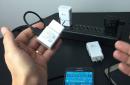
And here is the adapter at my home!

The kit includes the adapter itself, a cable for connecting to the radio and a USB cable.
The length of the cable for connecting to the radio is only 40 cm, which immediately imposes restrictions on the location of the adapter in the car - it has to be placed directly behind the radio, you can’t even reach the glove compartment with it.
The adapter is about the size of a cigarette box. A simple plastic box with a protruding cable for connecting devices or an AUX cable. However, after I connect the adapter to the radio, no one else will see it.
Additionally, I took an AUX cable with a minijack at the end (+500r)

A few more photos
Connector for connecting additional devices, AUX cable or bluetooth adapter 
Mom on adapter 
Dad on cable 
Connector for radio RD4 
Do not open, guarantee 
Installation
Radio tape recorder RD4, unscrew the two screws with a hexagon and take out the radio tape recorder.
There are two suitable connectors at the back, one of them will not work - checked;)
The photo shows the required connector. It already has wiring for connecting the changer, so we pull out the installed connector and turn on ours. 
We connect the cable with the adapter, turn on the ignition and miracle - everything worked immediately!!! Moreover, the volume level is approximately the same as from the built-in CD. 
But then we begin to think about where to connect the USB cable. The easiest way in my case turned out to be to route the cable under the steering wheel into the small glove compartment to the left of the driver. 
The adapter itself was put into a niche behind the left of the radio. There is not much space there; after installing the radio in place, the adapter was clamped there with cables, so there was no need to secure the adapter additionally.
On all forums they write that the radio requires activation of the changer in the service. For me, everything turned out to be much simpler. After turning on, the radio itself determined that a changer was connected to it and it became possible to select it through the input switch (radio/CD/changer).
As it turned out, activation is needed not for the radio, but for the display so that it can reflect information for the changer.
But six months ago I and the Chinese, well done, sent a display with all the activated functions. So everything worked for me without additional activation.
Adapter operation
Sound quality. Comparable to a CD player. The standard acoustics in the car are quite mediocre, so you definitely won’t hear the difference with the standard CD player in my car.Switching speed. Less than a couple of seconds after turning on the ignition on a flash drive with a couple of dozen catalogs. They write on the forums that with several hundred directories the speed is lower. The adapter remembers where it was playing before it was turned off and starts playing from the same place. This property is valuable for those who like to listen to audiobooks. The adapter remembers the location from the last 4 flash drives/
Switching tracks. In a fraction of a second, there is no difference whether the track is located in the same or another directory. There are no extraneous sounds during switching.
Replacing a flash drive. With the radio running, take out the flash drive and insert a new one. It is detected within a couple of seconds and immediately starts playing. During replacement, a very quiet short trill may sound.
The adapter understands 32 directories, which can have 32 subdirectories, each of which can contain up to 99 files. But I soon realized that my disc switch only switches the first six discs. Although in Random mode the adapter sees all directories.
I asked a question on the Trioma forum, support responded very quickly and offered options for organizing directories. The problem turned out to be that on the RD4 the buttons, although they perform the Disc+/Disk- function, in reality they send commands to directly select disk 1-6 to the adapter. So these buttons can only switch 6 root directories or 6 subdirectories.
And it’s not possible to manage 1024 directories on my radio. You can manage only 32*6=192 directories;)
The description says that the FF/FR buttons perform a dual function - changing directories/subdirectories and rewinding.
But on the RD4 Track+/Track- are combined with FF/FR and for the adapter these buttons have a triple purpose:
1. Short press - Track+/Track-
2. Press for 2-3 seconds, release when the sound will disappear from the current track - switch directory
3. Long press >3 seconds, there is an accelerated muffled sound - rewind
The time is approximate, you need to focus on the sound
Even before the purchase, I assumed that I would store one large megaflash drive with hundreds of catalogs. But now I see that it is more convenient to have several flash drives with different selections.
I have this now:
1. Russian pop music 80-90s
2. Foreign pop music 80-90s
3. Instrumentals
Total. For relatively little money, I got a glitch-free adapter with good sound quality and simple, intuitive controls. I am very pleased with the purchase, Trioma - well done!!!
Additional links
Mini FAQ
Some questions remained outside of this review; I decided to include them in a separate minifak. I will also add questions that arise in the comments here.- What needs to be done to ensure that the names (file names, tags, or anything at all) are shown on the display?
- Triom adapters certainly “see” tags, file names, and folder names. Where possible, they display text strings on the standard displays of radios: BMW and all cars with an optical MOST bus. Perhaps soon text output will be implemented for some Toyota/Lexus devices.
- CD changers do the job without any problems.
- I'm afraid you are mistaken: we do not know any external changers other than the models listed above that cope with this task. Changers built into the head unit are a different matter, where the text is output directly to the display controller - this is a completely different mechanism.
- Is it possible to connect additional devices to the Trioma Flipper 2 adapter?
- You can connect either an AUX-minijack 3.5 male adapter cable to the adapter
11
I have a Linux application for which I would like to automate some tests and its state needs to change based on the state of certain devices, i.e. USB devices, WLAN devices, WAN devices. However, we no longer have physical USB, WLAN, WAN, etc. devices, so I need to figure out a way to test this program without actually connecting physical devices, turning them on/off, etc.
I start with easy creation a virtual USB device that I can control from userspace, but there is a fundamental lack of knowledge on my part that is preventing me from taking any of the similar threads on these forums and applying them to my project. I feel like I need to create some kind of virtual USB driver and then associate it with some user level program, not usbfs. However, even if I create this virtual driver, how do I "mount" this device from user space and have my program registered with this specific driver? Is what I'm trying to do even possible?
2 answers
Sorting:
Activity
0
Can't you test the application in a virtual environment using VMWare? You can then "connect" any virtual device on your computer to the guest virtual machine and test the application this way.
8
The best way is to use drivers and hardware for Linux gadgets that allow you to be a USB device. The gadget driver allows the computer to “pretend” to be any device. Then your system under test has one USB cable OTG for gadget. You don't even need to unplug the cable if your gadget has the right hardware. The "gadget box" can be your desktop/laptop under Linux control(if it supports USB OTG) or even an Android phone or Raspberry Pi. (Be careful that USB cables suck out. Just because the cable fits does not mean it is properly connected to the USB OTG.).
Once you have the USB OTG hardware enabled, the gadget boxes are all software:
1) If the device under test supports OTG, make sure that your gadget is not trying to and is not a USB host. (Then your device under test will become a USB client.) I.e. make sure things like usb_storage are not loaded automatically.
2) The kernel supports gadgets for USB hubs, USB-Ethernet, USB-serial ports and USB storage devices. Just load the necessary modules into your gadget and it “just works”. For example, to create a USB drive, do something like this: "insmod g_file_storage.ko file=/dev/ram0". The far side will think you have connected a USB drive.
For serial devices, the gadget can run in user space code that "picks up the handset" to "/Dev/USBx" and talks to the device under test. (Apparently emulating a 4G modem or any other.)
Tons of devices are truly "USB-to-serial" under the hood because the manufacturer was too lazy to understand USB.
3) With a little re-compilation or configuration, you can use these universal devices for gadget, ID or return various strings supplier, etc. It will not be the same as "testing on real hardware", but at least you're testing the standard version of these devices.
4) For device types that aren't in the kernel yet (like Wi-Fi or whatever), you're on your own. With enough blood sweat and tears, you can write your own type of gadget. (Ideally, use as much as possible in user space and only handle critical components in the kernel..)