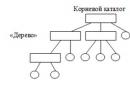
USB (Universal Serial Bus - Universal Serial Bus) The whole variety of USB 2.0 connectors is shown in the picture below. The picture is clickable.
For the avoidance of doubt: In all tables, the view of the connector is given from its external, working side (and not from the mounting side!), unless otherwise specified. The insulating parts of the connector are marked in light grey, the metal parts are marked in dark grey, and the connector cavities are marked in white.
Well, a simplified, so to speak, practical scheme:


The name of this or that connector is supplied with letter indices.
connector type:
- A - active, powering device (computer, host)
- B - passive, connected device (printer, scanner)
"Gender" of the connector:
- M (male) - plug, "dad"
- F (female) - nest, "mother"
Connector size:
For example: USB micro-BM-plug (M) for connecting to a passive device (B); micro size.
USB connector pinout (jacks and plugs)
The purpose of the wires in the USB cable is as follows:
- Red VBUS (+5V, Vcc - Voltage Collector Collector) +5 volts DC voltage with respect to GND. Maximum current - 500 mA
- White D-(-Data)
- Green D+ (+Data)
- Black GND - common wire, "ground", "minus", 0 Volt
The mini and micro connectors contain 5 pins:
- Red VBUS
- White D-
- Green D+
- ID - not used in connectors "B"; in connectors "A" shorted to GND to support the "OTG" function
- Black GND
Among other things, the cable contains (though not always) a bare Shield wire - a case, a screen, a braid. This wire is not assigned a number.
Good news
A reversible micro-USB plug is announced on the Internet, which, like USB 3.1 Type-C, does not require a clear orientation of ± 180 ° when connected to the socket.

Mouse and Keyboard Cord Pinout
Some mice and keyboards may have cable colors that are different from the standard. Detailed article on custom colors: "USB custom colors in mouse and keyboard cords"
Read also about connecting mice and keyboards to the PS/2 port
How to unsolder USB?
Well, with conventional USB, everything is simple - you take an image of the front of the connector in mirror image and solder it.
 The wiring of the USB mini and USB micro plugs from the mounting side is shown in the picture below. If you are soldering a simple data cable (for connecting a PC and a mobile phone / smartphone / tablet), then do not use the 4th contact. When soldering OTG cables(for connecting flash drives and other things to a smartphone) Connect the 4th contact to the 5th.

The mini and micro connectors contain 5 pins. In connectors of type "B" the fourth contact is not used. In type "A" connectors, the fourth pin is shorted to GND. And the GND contact itself gets an honorable fifth place.
And here is the complete diagram of the USB cable with a screen.

Related materials:
All USB related content All Charger related content All Computer related content
Tags: USB, Cable, Computer, Mobile, Connector, Pinout (Wiringout)
rones.su
Pinout of USB ports, pinout of micro usb, mini connector for charging
Everything is currently mobile devices and desktop electrical appliances have data ports in their arsenal. Modern gadgets can not only exchange information via USB or micro-USB, but also charge batteries. In order to conduct a competent pinout of the contacts, first you need to study the diagrams and colors of the wiring.
USB Cable Wire Colors
Connector diagram for USB 2.0
On the diagram you can see several connectors that differ from each other in a certain way. For example, an active (power) device is denoted by the letter A, and a passive (pluggable) device is denoted by the letter B. Active devices include computers and hosts, and passive devices are printers, scanners, and other devices. It is also customary to separate connectors by gender: M (male) or “male” is a plug, and F (female) or “mother” is a connector socket. There are formats in size: mini, micro and without marking. For example, if you see the designation “USB micro-VM”, then this means that the plug is designed to connect to a passive device using the micro format.
To pin out sockets and plugs, you will need knowledge about the purpose of the wires in the USB cable:
- the red VBUS ("plus") carries a constant voltage of 5 volts relative to GND. Minimum force value electric current for it is 500 mA;
- the white wire is connected to the "minus" (D-);
- the green wire is attached to the "plus" (D +);
- The black color of the wire means that the voltage in it is 0 Volts, it carries a negative charge and is used for grounding.
In mini and micro formats, the connectors contain five pins each: red, black, white and green wires, as well as ID (which is closed to GND in type A connectors, and not used at all in connectors B).
Sometimes you can also find a bare Shield wire in the USB cable. This wire is not numbered.
If you use a table in your work, then the connector in it is shown from the outer (working) side. The insulating parts of the connector are light gray, the metal parts are dark gray, and the cavities are marked in white.
In order to carry out the correct USB desoldering, you need to mirror the image of the front of the connector.
Connectors for mini and micro formats on USB consist of five pins. Therefore, the fourth contact in the type B connectors will not have to be used in operation. This contact in type A connectors closes with GND, and for GND itself, the fifth one is used.

As a result of not tricky manipulations, you can independently make a pinout for USB ports of various formats.
Usb wiring version 3.0 is distinguished by the addition of four colored wires and an additional ground. Due to this, the USB 3.0 cable is noticeably thicker than its younger brother.

Scheme USB connections devices to each other and unsoldering device plugs:

volt-index.ru
USB connector pinout: normal, mini, micro
In our age computer technology, smartphones and gadgets, it is difficult to find a person who does not know what USB connectors are. Also, almost everyone understands such words as mini- and micro-USB connector. After all, we use such things almost daily, which is natural. Similar connectors are on charger, and on all peripheral devices of the computer.
But what to do if the soldering has moved away at the base, and there is no way to even understand what color and what contact was soldered? Here it is already necessary to apply knowledge, and which ones, now we will try to figure it out.
The desoldering of such a plug, or, in other words, the pinout of a USB wire, in its essence does not carry anything super complicated. With the consistency and colors figured out, anyone who can handle a soldering iron can do the job.
But first you need to understand what a USB plug is.
 Types of USB plugs
 What is a USB connector?
At its core, this is a connector with many possibilities, ranging from USB power to the transfer of complex information data. A similar cable replaced the previously used options for connecting to a computer (PS / 2 ports, etc.). It is used today for all devices connected to a personal computer, be it a mouse, flash drives, printer, camera or modem, joystick or keyboard - USB cables have become truly universal.
There are three types of such connectors:
- 1.1 - its purpose is already outdated peripheral devices with the ability to transfer information at only one and a half megabits per second. Of course, after a slight refinement by the manufacturer, the transfer rate rose to 12 Mbps, but with higher speed options, it still could not stand the competition. Still, when Apple already had a connector that supports 400 Mbps. Now there are also such types, but there are very few of them, since faster USB wires, mini USB appeared long ago, and indeed, USB speed occupies a special place in human life. Everyone is in a hurry somewhere, in a hurry to live, there are people who practically do not sleep, and therefore, the faster the information is downloaded, the more preferable the connector, right?
- 2.0. At the end of the last century, the second generation of such connectors was released. Here the manufacturer has already tried - the transmission speed has increased to almost 500 Mbps. And it was intended mainly for sophisticated gadgets, like a digital video camera.
- 3.0 - this is really high technology. The maximum data transfer rate of 5 Gb / s provided this USB connector with demand, which practically brought the first and second versions to zero. In the third series, the number of wires was increased to nine versus four. However, the connector itself has not been modified, and therefore the first and second series views can still be used with it.
Pinout designations
Considering the pinout diagram, it is necessary to understand all the designations that are present on it. Usually stated:
USB pinout options
- Type of connector - it can be active (A) and passive (B). The connection of a printer, scanner, etc. is called passive. In general, a connector that only works to receive information. Through the active it is possible to receive and transmit data.
- The shape of the connector is "mother", that is, a socket (F), and "father" - a plug (M).
- Connector sizes are regular, mini and micro.
For example, USB AM, that is, an active USB plug.
The wires should be arranged by color as follows (from left to right):
- Red wire - positive, constant voltage of 5V. with a maximum current of 500 milliamps.
- White wire -data-
- Green wire - data+
- Black wire - this wire is common, "ground", "minus". There is no voltage on it.
But the mini and micro connectors include 5 wires with the following arrangement:
- Wires of red, white and green colors - are located similarly to the first option.
- ID - this wire is free in connectors "B". In "A" it must be shorted to a black wire.
Sometimes a separate wire without insulation may be present in the connector - this is the so-called "ground", which is soldered to the body.
According to the presented schemes, the outer side is visible here. In order to solder the plug yourself, you need to take a mirror image of the picture, and as it probably became clear, the microUSB pinout is no more complicated than that of conventional USB connectors.
By the way, if the damaged parts of the cable are supposed to be used only for charging mobile phones, it will be more convenient, after looking at the colors of the wires, to solder only black and red. This connector is quite enough for the phone, it will charge it. What to do with the rest of the wires? You don't need to do anything with them.
domelectrik.com
Unsoldering the USB connector. Desoldering scheme:
The USB connector wiring has been developed since 1994, while the development team consisted of engineers from leading companies in the field of IT technologies - Microsoft, Apple, Intel and others. In the process of conducting research, one task was pursued - to find a universal port that could be used for most devices.
Thus, users were provided with a USB connector, which was almost immediately supported by various developers and began to be actively used in the most different devices starting from personal computers and ending with mobile gadgets. However, it so happened that cables with such connectors could not be used everywhere, and they themselves were different, and therefore some need to desolder the mini-USB connector in order to make the appropriate adapter.
At the same time, few people know how this procedure should be carried out correctly.
Concepts you need to know

Unsoldering a USB connector begins by learning the basic concepts:
- VCC is the positive potential contact of the power supply. For modern USB cables, the indicator of this contact is +5 Volts, while it is worth noting that in radio electrical circuits such an abbreviation fully corresponds to the supply voltage of PNP, as well as NPN transistors.
- GND - contact of the negative potential of the power supply. In modern equipment, including also various models motherboards, this device connected to the body in order to provide effective protection against static electricity or any external sources of electromagnetic interference.
- D- - information contact having zero potential, relative to which information is broadcast.
- D+ - information contact having a logical unit. This pin is used to relay information from the host to the device or vice versa. On the physical level this process represents the transmission of rectangular pulses with a positive charge, while the pulses have different amplitudes and duty cycles.
- Male - the plug of this connector, which is often called "dad" among modern users who unsolder the USB connector for a mouse and other devices.
- Female - the socket into which the plug is inserted. Called "mom" by users.
- RX - information reception.
- TX - information transmission.
USB-OTG
OTG is a way to connect two peripheral devices via a USB cable without the need for a computer. Also, such a pinout of a micro-USB connector is often called USB-host in professional circles. In other words, a flash drive or some HDD in this way, they can directly connect to a tablet or mobile phone in the same way as a full-fledged personal computer.

In addition, mice or keyboards can be connected to gadgets if they support the ability to use them. Often, cameras and other gadgets are connected to printers in this way.
What are its limitations?
The limitations that such a pinout of the micro USB connector has are as follows:

For example, if we are talking about connecting a USB flash drive to the phone, then in this case the USB_AF-USB_AM_micro adapter is most often used. In this case, a flash drive is inserted into the socket, while the plug is connected to the mobile phone.
Cable Feature

The main feature that distinguishes the soldering of the USB connector in the OTG format is that in the plug, pin 4 must be closed with pin 5 without fail. In a standard data cable, nothing is soldered to this pin at all, but this plug is called USB-BM micro. It is for this reason that you need to get to the fourth pin, and then use a jumper to connect it to the GND wire. After this procedure, the plug will be renamed to USB-AM micro. It is the presence of a jumper between these contacts in the plug that allows the device to determine that some peripheral device is going to be connected to it. In the event that the device does not see this jumper, it will act as a passive device, and any flash drives connected to it will simply be completely ignored.
How are devices defined?

Many people believe that when connecting in OTG mode, both devices automatically determine which of them will be the host and which will be the slave. In reality, in this case, only the user determines who exactly in this case will be the master, since into which device the plug equipped with a jumper between 4 and 5 contacts will be plugged, one of them will be the host.
How to make it?
Through the translucent insulation, you can see several multi-colored wires. You will need to melt the insulation near the black wire, then solder one end of the jumper to the GND pin. On the opposite side, you can see a white wire, as well as an unused contact. In this case, we need to melt the insulation near the unused contact, and then solder the second end of the jumper to it.
It is worth noting that the wiring diagram for the micro USB connector is much simpler.
The twisted plug, which you equipped with a jumper, will need to be insulated, for which a specialized heat shrink tube is used. After that, you will just need to take the "mother" from the extension cord and solder it to our plug color by color. If the cables are shielded, then you will also need to connect the shields, among other things.
Can it be charged?
If peripherals are connected to the device via OTG, then in this case it will have to power it, which can significantly reduce the overall duration of the device from the battery built into it. In this regard, many are wondering whether it is possible to recharge such a device through an external source. It is possible, but this requires support for a special mode in the device, as well as a separate wiring for the USB connector for charging.

In fact, the charging mode is most often provided by modern gadget developers, but not everyone allows such a procedure. At the same time, it should be noted that in order to switch to such a charging mode, a separate USB connector wiring diagram must be used, in which the contacts are closed through a separate resistor.
- in order to use the USB inputs installed in front of the system case, they must first be connected to the PC motherboard. This publication will discuss how to properly organize and perform such a connection.
Modern motherboards now mostly come with four, six, or eight USB connectors. But they are installed directly into the system board, as a rule, there are only two or four connectors on the back side. In this regard, in most cases we have a couple of USB ports left on the motherboard. These connectors are usually made in nine or ten pin connectors.
USB pinout on motherboard
One of the most significant problems is that global manufacturers do not use a common standard for motherboards in their manufacture. Therefore, the assignment of each pin in the connectors from different board manufacturers may differ in functionality from motherboards from another brand. For this reason, personal connectors are used for any USB connector wire on the front panel of the system unit.
Unsoldering the USB 2.0 connector on the motherboard
On each connector housing there are special designations like this: + 5V, D+, D- and GND (housing), but the values \u200b\u200bare indicated slightly differently, although the essence is the same.
| No. pin | Wire color | Name | Description |
|---|---|---|---|
| 1 | Red | 5V,VCC,Power | Nutrition |
| 2 | Red | 5V,VCC,Power | Nutrition |
| 3 | White | D- | Data- |
| 4 | White | D- | Data- |
| 5 | Green | D+ | Data+ |
| 6 | Green | D+ | Data+ |
| 7 | Black | GND | Earth |
| 8 | Black | GND | Earth |
| 9 | — | Key(No pin) | Key |
| 10 | Grey | GND | Earth |
All you have to do is set each of the wires (+5V, D+, D- and GND) to right places as shown above.
Unsoldering the USB 3.0 connector on the motherboard
| No. pin | Name | Description | No. pin | Name | Description |
|---|---|---|---|---|---|
| 1 | IntA_P2_D+ | Data+ | 2 | ID | Identifier |
| 3 | IntA_P2_D- | Data- | 4 | IntA_P1_D+ | Data+ |
| 5 | GND | Earth | 6 | IntA_P1_D- | Data- |
| 7 | IntA_P2_SSTX+ | Data+ | 8 | GND | Earth |
| 9 | IntA_P2_SSTX- | Data- | 10 | IntA_P1_SSTX+ | Data+ |
| 11 | GND | Earth | 12 | IntA_P1_SSTX- | Data- |
| 13 | IntA_P2_SSRX+ | Data+ | 14 | GND | Earth |
| 15 | IntA_P2_SSRX- | Data- | 16 | IntA_P1_SSRX+ | Data+ |
| 17 | Vbus | Nutrition | 18 | IntA_P1_SSRX- | Data- |
| 19 | Key(No pin) | Key | 20 | Vbus | Nutrition |
How to connect the front panel to the motherboard
It has been developed since 1994, while the development team consisted of engineers from leading companies in the field of IT technologies - Microsoft, Apple, Intel and others. In the course of research, one task was pursued - to find a universal port that could be used for most devices.
Thus, users were provided with a USB connector, which was almost immediately supported by various developers and began to be actively used in a variety of devices, from personal computers to mobile gadgets. However, it so happened that cables with such connectors could not be used everywhere, and they themselves were different, and therefore some need to desolder the mini-USB connector in order to make the appropriate adapter.
At the same time, few people know how this procedure should be carried out correctly.
Concepts you need to know
Unsoldering a USB connector begins by learning the basic concepts:
- VCC - positive potential contact For modern USB cables, the indicator of this contact is +5 Volts, while it is worth noting that in radio electrical circuits such an abbreviation fully corresponds to the supply voltage of PNP, as well as NPN transistors.
- GND - contact of the negative potential of the power supply. In modern equipment, including also various models of motherboards, this device is connected by a case in order to provide effective protection against static electricity or any external sources of electromagnetic interference.
- D- - information contact having zero potential, relative to which information is broadcast.
- D+ - information contact having a logical unit. This pin is used to relay information from the host to the device or vice versa. At the physical level, this process is the transmission of rectangular pulses with a positive charge, while the pulses have different amplitudes and duty cycles.
- Male - the plug of this connector, which is often called "dad" among modern users who unsolder the USB connector for a mouse and other devices.
- Female - the socket into which the plug is inserted. Called "mom" by users.
- RX - information reception.
- TX - information transfer.
USB-OTG
OTG is a way to connect two peripheral devices via a USB cable without the need for a computer. Also, such a pinout of a micro-USB connector is often called USB-host in professional circles. In other words, a flash drive or some kind of hard drive can thus be directly connected to a tablet or mobile phone in the same way as a full-fledged personal computer.

In addition, mice or keyboards can be connected to gadgets if they support the ability to use them. Often, cameras and other gadgets are connected to printers in this way.
What are its limitations?
The limitations that such a pinout of the micro USB connector has are as follows:

For example, if we are talking about connecting a USB flash drive to the phone, then in this case the USB_AF-USB_AM_micro adapter is most often used. In this case, a flash drive is inserted into the socket, while the plug is connected to the mobile phone.
Cable Feature

The main feature that distinguishes the soldering of the USB connector in the OTG format is that in the plug, pin 4 must be closed with pin 5 without fail. In a standard data cable, nothing is soldered to this pin at all, but this plug is called USB-BM micro. It is for this reason that you need to get to the fourth pin, and then use a jumper to connect it to the GND wire. After this procedure, the plug will be renamed to USB-AM micro. It is the presence of a jumper between these contacts in the plug that allows the device to determine that some peripheral device is going to be connected to it. In the event that the device does not see this jumper, it will act as a passive device, and any flash drives connected to it will simply be completely ignored.
How are devices defined?

Many people believe that when connecting in OTG mode, both devices automatically determine which of them will be the host and which will be the slave. In reality, in this case, only the user determines who exactly in this case will be the master, since into which device the plug equipped with a jumper between 4 and 5 contacts will be plugged, one of them will be the host.
How to make it?
Through the translucent insulation, you can see several multi-colored wires. You will need to melt the insulation near the black wire, then solder one end of the jumper to the GND pin. On the opposite side, you can see a white wire, as well as an unused contact. In this case, we need to melt the insulation near the unused contact, and then solder the second end of the jumper to it.
It is worth noting that the wiring diagram for the micro USB connector is much simpler.
The twisted plug, which you equipped with a jumper, will need to be insulated, for which a specialized heat shrink tube is used. After that, you will just need to take the "mother" from the extension cord and solder it to our plug color by color. If the cables are shielded, then you will also need to connect the shields, among other things.
Can it be charged?
If peripherals are connected to the device via OTG, then in this case it will have to power it, which can significantly reduce the overall duration of the device from the battery built into it. In this regard, many are wondering whether it is possible to recharge such a device through an external source. It is possible, but this requires support for a special mode in the device, as well as a separate wiring for the USB connector for charging.

In fact, the charging mode is most often provided by modern gadget developers, but not everyone allows such a procedure. At the same time, it should be noted that in order to switch to such a charging mode, a separate USB connector wiring diagram must be used, in which the contacts are closed through a separate resistor.
The USB cable pinout refers to the description of the internals of the Universal Serial Bus. This device is used to transfer data and charge batteries of any electronic devices: mobile phones, players, laptops, tablet computers, tape recorders and other gadgets.
Carrying out high-quality pinouts requires knowledge and the ability to read diagrams, orientation in the types and types of connections, you need to know the classification of wires, their colors and purpose. Long and uninterrupted operation of the cable is ensured by the correct connection of the wires of 2 connectors USB And mini USB.
Types of USB connectors, main differences and features
The Universal Serial Bus comes in 3 versions - USB 1.1, USB 2.0 and USB 3.0. The first two specifications are fully compatible with each other, the 3.0 tire has a partial overlap.
USB 1.1 is the first version of the device used for data transfer. The specification is used only for compatibility, since 2 operating modes for data transfer ( Low-speed and Full-speed) have a low rate of information exchange. Low-speed mode with a data transfer rate of 10-1500 Kbps is used for joysticks, mice, keyboards. Full-speed is used in audio and video devices.
USB 2.0 added a third mode of operation - High-speed for connecting storage devices and video devices of a higher organization. The connector is marked with HI-SPEED on the logo. The information exchange rate in this mode is 480 Mbps, which is equal to the copy speed of 48 Mbps.
In practice, due to the design and implementation of the protocol, throughput the second version turned out to be less than the declared one and is 30-35 MB / s. The cables and connectors of the Universal Bus Specifications 1.1 and Generation 2 have an identical configuration.
The third-generation universal bus supports 5 Gb/s, which is equal to 500 MB/s copy speed. It is available in blue, making it easy to identify which plugs and sockets belong to the upgraded model. Bus 3.0 current increased from 500mA to 900mA. This feature allows you not to use separate power supplies for peripheral devices, but to use the 3.0 bus to power them.
Specifications 2.0 and 3.0 are partially compatible.
Classification and pinout
With descriptions and designations in the tables of USB connectors, it is assumed by default that the view is shown from the outside, working side. If the view from the mounting side is supplied, then this is specified in the description. In the scheme, insulating elements of the connector are marked in light gray, metal parts are marked in dark gray, cavities are indicated in white.

Despite the fact that the serial bus is called universal, it is represented by 2 types. They perform different functions and provide compatibility with devices with improved performance.
Type A includes active, powered devices ( computer, host), to type B - passive, connected equipment ( printer, scanner). All sockets and plugs of Gen 2 and Rev 3.0 Type A busbars are designed to work together. The 3rd generation bus connector type B is larger than the version 2.0 type B plug, so a device with a universal bus 2.0 type B connector is connected using only a USB 2.0 cable. Connecting external equipment with 3.0 type B connectors is done with both types of cables.
Classic type B connectors are not suitable for connecting small electronic equipment. Connection of tablets, digital equipment, mobile phones is carried out using miniature connectors Mini-USB and their improved modification Micro-USB. These connectors have reduced plug and socket dimensions.
The latest modification of the USB connectors is type C. This design has the same connectors at both ends of the cable, it is characterized by faster data transfer and more power.
Pinout USB 2.0 connector types A and B
Classic connectors contain 4 types of contacts, in mini- and microformats - 5 contacts. Wire colors in USB 2.0 cable:
- +5V ( red VBUS), voltage 5 V, maximum current 0.5 A, designed for power supply;
- D-( white) Data-;
- D+( green) Data+;
- GND ( black), voltage 0 V, is used for grounding.

For mini format: mini-USB and micro-USB:
- Red VBUS (+), voltage 5 V, current 0.5 A.
- White (-), D-.
- Green (+), D+.
- ID - for type A they are closed to GND, to support the OTG function, and for type B they are not used.
- Black GND, voltage 0V, used for ground.
Most cables have a Shield wire, it has no insulation, it is used as a shield. It is not marked and is not assigned a number. The universal bus has 2 types of connector. They have the designation M ( male) and F ( female). Connector M ( dad) is called a plug, it is inserted, connector F ( Mother) is called a nest, they are inserted into it.
USB 3.0 pinout types A and B
Bus version 3.0 has a 10 or 9 wire connection. 9 pins is used if the Shield wire is missing. The arrangement of contacts is made in such a way that devices of earlier modifications can be connected.
USB 3.0 pinout:
- A - plug;
- B - nest;
- 1, 2, 3, 4 - contacts that match the pinout in specification 2.0 have the same color scheme;
- 5, 6 contacts for data transfer via the SUPER_SPEED protocol are designated SS_TX- and SS_TX+, respectively;
- 7 – grounding GND;
- 8, 9 – pads of wires for receiving data via the SUPER_SPEED protocol, pin designations: SS_RX- and SS_RX+.

Micro USB pinout
The Micro-USB cable has 5 pad connectors. A separate mounting wire is supplied to them in the insulation of the desired color. In order for the plug to fit accurately and tightly into the socket, the upper shielding part has a special chamfer. The micro USB contacts are numbered 1 to 5 and read from right to left.
The pinouts of the micro- and mini-USB connectors are identical, presented in the table:
The shield wire is not soldered to any pin.

Mini-USB Pinout
Mini-A and Mini-B connectors appeared on the market in 2000, using the USB 2.0 standard. To date, little used due to the emergence of more advanced modifications. They were replaced by micro connectors and USB type C models. The mini connectors use 4 shielded wires and an ID function. 2 wires are used for power: supply +5 V and ground GND. 2 wires for receiving and sending differential data signals, designated D+ and D-pin. Data+ and Data- signals are transmitted via . D+ and D- always work together, they are not separate simplex connections.
USB connectors use 2 types of cables:
- shielded, 28 AWG stranded, rated at 28 AWG or 20 AWG without twist;
- unshielded, 28 AWG without twist, 28 AWG or 20 AWG without twist.

The length of the cable depends on the power:
- 28 - 0.81 m;
- 26 - 1.31 m;
- 24 - 2.08 m;
- 22 - 3.33 m;
- 20 - 5 m.
Many manufacturers of digital equipment develop and complete their products with connectors of a different configuration. This can cause charging problems. mobile phone or other devices.
Universal Serial Bus (USB) pinout diagram
USB connector wiring diagram
USB connectors wiring diagram (cable and device)

USB connectors wiring diagram (cable and device)
USB signals are transmitted over two wires (twisted pair) of a shielded four-core cable.
VBUS - voltage +5 Volts of the power circuit, GND - contact for connecting the "case" of the power circuit. The maximum current consumed by the device through the power lines of the USB bus must not exceed 500 mA. Data is transferred via the D- and D+ pins of the USB connector. The differential mode of data transfer is the main one for USB.
USB cable connectors
The USB cable uses special USB connectors. The USB cable is directional, so for correct connection, USB connectors have a different configuration. There are two types of USB connectors: Type A (see Fig.7 and Fig.8) and Type B (see Fig.9, Fig.10 and Fig.11).

Fig.7. Ordinary USB connector Cable Type A
In accordance with the USB 1.0 specification, Type A connectors are used to connect "to the host" i.e. installed on the side of the USB controller or hub.

Fig.8. "Company" connector USB cable Type A
According to the USB 1.0 specification, Type B connectors are used to connect "to the device" i.e. for connecting peripheral devices.

Fig.9. Standard USB cable connector Type B. This connector is suitable, for example,
to connect a printer

Fig.10. Regular USB mini cable connector Type B

Fig.11. Micro USB cable connector Type B. In the figure, below the USB symbol, the designation Type B is clearly visible.
On Fig.12. and Fig.13. USB cables shown. These USB cables are equipped with a regular Type A USB cable connector and a Type B USB mini cable connector.

Fig.12. USB cables are equipped with a regular Type A USB cable connector (shown on the left) and a USB mini Type B cable connector (shown on the right). Type B is designated as B

Fig.13. USB cables are equipped with a regular Type A USB cable connector (shown on the left) and a USB mini Type B cable connector (shown on the right). Type B is designated as b

Fig.14. USB cable equipped with a miniature connector called micro USB
USB supports hot (power on) plugging and unplugging devices. This is achieved by increasing the length of the grounding contact of the connector in relation to the signal contacts, see Fig.15. When connecting the USB connector, the ground contacts are closed first, the potentials of the cases of the two devices are equalized, and further connection of the signal conductors does not lead to overvoltages, even if the devices are powered by different phases of the three-phase power network.

Fig.15. The length of the grounding contact (in the figure, pin 4 GND at the top) of the connector is increased in relation to the signal (in the figure, pin 3 D+ at the bottom) contacts. The top contact is longer than the bottom. This allows you to connect and disconnect devices without turning off the power (the so-called "hot" connection and disconnection)

Fig.15.a. The length of the USB power contacts of the flash card connector (in the figure, the extreme contacts) is increased in relation to the signal (in the figure, the middle contacts) contacts. This allows you to connect and disconnect devices without turning off the power (the so-called "hot" connection and disconnection)
Mating parts of USB connectors are located on peripheral devices connected via USB, see Fig.16. and Fig.17.

Fig.16. Connector for connecting the USB cable connector. The USB symbol is clearly visible

Fig.17. Connector for USB cable connector mini Type B

Fig.18. Size comparison of USB connectors. Regular USB cable connector Type A (left picture), USB mini cable connector Type B (center picture) and USB micro cable Type B (right picture). Type B is designated as B