A low frequency amplifier (LF) is an integral part of most radio devices such as a TV, player, radio and various household appliances. Let's consider two simple circuits two-stage ULF on.
The first version of ULF on transistors
In the first version, the amplifier is built on silicon npn transistors conductivity. The input signal comes through variable resistor R1, which in turn is a load resistor for the signal source circuit. connected to the collector circuit of transistor VT2 of the amplifier.
Setting up the amplifier of the first option comes down to selecting resistances R2 and R4. The resistance value must be selected such that the milliammeter connected to the collector circuit of each transistor shows a current in the region of 0.5...0.8 mA. According to the second scheme, it is also necessary to set the collector current of the second transistor by selecting the resistance of resistor R3.
In the first option, it is possible to use transistors of the KT312 brand, or their foreign analogues, however, it will be necessary to set the correct voltage bias of the transistors by selecting resistances R2, R4. In the second option, in turn, it is possible to use silicon transistors of the KT209, KT361 brands, or foreign analogues. In this case, you can set the operating modes of the transistors by changing the resistance R3.
Instead of headphones, it is possible to connect a high-impedance speaker to the collector circuit of transistor VT2 (both amplifiers). If you need to get more powerful sound amplification, you can assemble an amplifier that provides amplification of up to 15 W.
Scheme No. 2
The circuit of our second amplifier is much more complicated, but it allows us to get better sound quality. This was achieved due to more advanced circuit technology, higher amplifier gain (and, therefore, deeper feedback), as well as the ability to adjust the initial bias of the output stage transistors.
The diagram of the new amplifier version is shown in Fig. 11.20. This amplifier, unlike its predecessor, is powered by a bipolar voltage source.
The input stage of the amplifier on transistors VT1-VT3 forms the so-called. differential amplifier. Transistor VT2 in a differential amplifier is a current source (quite often in differential amplifiers a conventional resistor of a fairly large value is used as a current source). And transistors VT1 and VT3 form two paths along which current from the source goes to the load.
If the current in the circuit of one transistor increases, then the current in the circuit of the other transistor will decrease by exactly the same amount - the current source maintains the sum of the currents of both transistors constant.
As a result, the transistors of the differential amplifier form an almost “ideal” comparison device, which is important for high-quality feedback operation. An amplified signal is supplied to the base of one transistor, and a feedback signal is supplied to the base of the other through a voltage divider on resistors R6, R8.
The antiphase “divergence” signal is isolated on resistors R4 and R5, and is supplied to two amplification circuits:
- transistor VT7;
- transistors VT4-VT6.
When there is no mismatch signal, the currents of both chains, i.e., transistors VT7 and VT6, are equal, and the voltage at the point of connection of their collectors (in our circuit, transistor VT8 can be considered such a point) is exactly zero.
When a mismatch signal appears, the transistor currents become different, and the voltage at the connection point becomes more or less than zero. This voltage is amplified by a composite emitter follower assembled on complementary pairs VT9, VT10 and VT11, VT12, and is supplied to the speakers - this is the output signal of the amplifier.
Transistor VT8 is used to regulate the so-called. quiescent current of the output stage. When the slider of the trimming resistor R14 is in the upper position according to the circuit, the transistor VT8 is completely open. In this case, the voltage drop across it is close to zero. If you move the resistor slider to the lower position, the voltage drop across transistor VT8 will increase. And this is equivalent to introducing a bias signal into the bases of the transistors of the output emitter follower. There is a shift in their operating mode from class C to class B, and, in principle, to class A. This, as we already know, is one of the ways to improve sound quality - you should not rely only on feedback.
Pay . The amplifier is assembled on a board made of single-sided fiberglass 1.5 mm thick with dimensions 50x47.5 mm. PCB layout in mirror image and the parts layout diagram can be downloaded. We look at the operation of the amplifier. Appearance amplifier is shown in Fig. 11.21.
Analogs and element base . In the absence of the necessary parts, transistors VT1, VT3 can be replaced with any low-noise ones with a permissible current of at least 100 mA, a permissible voltage not lower than the supply voltage of the amplifier and the highest possible gain.
Especially for such circuits, the industry produces transistor assemblies, which are a pair of transistors in one package with the maximum similar characteristics- this would be an ideal option.
Transistors VT9 and VT10 must be complementary, as well as VT11 and VT12. They must be designed for a voltage of at least twice the amplifier supply voltage. Have you forgotten, dear radio amateur, that the amplifier is powered by a bipolar voltage source?
For foreign analogues, complementary pairs are usually indicated in the documentation for the transistor, for domestic devices - you will have to sweat on the Internet! Transistors of the output stage VT11, VT12 must additionally withstand a current not less than:
I in = U / R, A,
U- amplifier supply voltage,
R- AC resistance.
For transistors VT9, VT10, the permissible current must be at least:
I p = I in / B, A,
I in- maximum current of output transistors;
B- gain of output transistors.
Please note that documentation for power transistors sometimes gives two gains - one for the “small signal” amplification mode, the other for the OE circuit. The one you need for the calculation is not the one for the “small signal”. Please also pay attention to the peculiarity of the KT972/KT973 transistors - their gain is more than 750.
The analogue you find must have no less gain - this is essential for this circuit. The remaining transistors must have a permissible voltage of at least twice the amplifier supply voltage and a permissible current of at least 100 mA. Resistors - any with a permissible power dissipation of at least 0.125 W. Capacitors are electrolytic, with a capacitance not less than specified and an operating voltage not less than the supply voltage of the amplifier.
Continue reading
Readers! Remember this author's nickname and never repeat his schemes.
Moderators! Before you ban me for insulting me, think that you “allowed an ordinary gopnik to the microphone, who should not even be allowed close to radio engineering and, especially, to teaching beginners.
Firstly, with such a connection scheme, a large D.C., even if the variable resistor is in the desired position, that is, music will be heard. And with a large current, the speaker is damaged, that is, sooner or later, it will burn out.
Secondly, in this circuit there must be a current limiter, that is, a constant resistor, at least 1 KOhm, connected in series with an alternating one. Any homemade product will turn the variable resistor knob all the way, it will have zero resistance and a large current will flow to the base of the transistor. As a result, the transistor or speaker will burn out.
A variable capacitor at the input is needed to protect the sound source (the author should explain this, because there was immediately a reader who removed it just like that, considering himself smarter than the author). Without it, only those players that already have similar protection at the output will work normally. And if it is not there, then the player’s output may be damaged, especially, as I said above, if you turn the variable resistor “to zero”. In this case, the output of the expensive laptop will be supplied with voltage from the power source of this cheap trinket and it may burn out. Homemade people love to remove protective resistors and capacitors, because “it works!” As a result, the circuit may work with one sound source, but not with another, and even an expensive phone or laptop can be damaged.
The variable resistor in this circuit should only be tuning, that is, it should be adjusted once and closed in the housing, and not brought out with a convenient handle. This is not a volume control, but a distortion control, that is, it selects the operating mode of the transistor so that there is minimal distortion and so that no smoke comes out of the speaker. Therefore, it should under no circumstances be accessible from the outside. You CANNOT adjust the volume by changing the mode. This is something to kill for. If you really want to regulate the volume, it’s easier to connect another variable resistor in series with the capacitor and now it can be output to the amplifier body.
In general, for the simplest circuits - and to make it work right away and not to damage anything, you need to buy a TDA type microcircuit (for example TDA7052, TDA7056... there are many examples on the Internet), and the author took a random transistor that was lying around in his desk. As a result, gullible amateurs will look for just such a transistor, although its gain is only 15, and the permissible current is as much as 8 amperes (it will burn out any speaker without even noticing).
They are becoming a thing of the past, and now, in order to assemble any simple amplifier, you no longer have to suffer with calculations and riveting printed circuit board large sizes.
Now almost all cheap amplification equipment is made on microcircuits. The most widespread are TDA chips for amplifying audio signals. Currently they are used in car radios, in active subwoofers, V home acoustics and in many other audio amplifiers and look something like this:


Pros of TDA chips
- In order to assemble an amplifier on them, it is enough to supply power, connect speakers and several radio elements.
- The dimensions of these microcircuits are quite small, but they will need to be placed on a radiator, otherwise they will get very hot.
- They are sold at any radio store. There are some things on Ali that are a little expensive if you buy them at retail.
- They have built-in various protections and other options, such as muting the sound, etc. But according to my observations, the protections do not work very well, so microcircuits often die either from overheating or from. So it is advisable not to short-circuit the pins of the microcircuit with each other and not to overheat the microcircuit, squeezing all the juices out of it.
- Price. I wouldn't say they are very expensive. In terms of price and functions, they have no equal.
Single-channel amplifier on TDA7396
Let's build a simple single-channel amplifier using the TDA7396 chip. At the time of writing, I took it at a price of 240 rubles. The datasheet for the chip said that this chip can output up to 45 Watts into a 2 Ohm load. That is, if you measure the resistance of the speaker coil and it is about 2 ohms, then it is quite possible to get a peak power of 45 watts from the speaker.This power is quite enough to arrange a disco in the room not only for yourself, but also for your neighbors and at the same time get mediocre sound, which, of course, cannot be compared with hi-fi amplifiers.
Here is the pinout of the microcircuit:

We will assemble our amplifier according to a typical diagram, which was attached in the datasheet itself:

We apply +Vs to leg 8, and nothing to leg 4. Therefore, the diagram will look like this:

Vs is the supply voltage. It can be from 8 to 18 Volts. “IN+” and “IN-” – here we serve the weak sound signal. We attach a speaker to the 5th and 7th legs. We set the sixth leg to minus.
Here is my wall mounted assembly

I did not use capacitors at the power input of 100nF and 1000uF, since I already have pure voltage coming from the power supply.
I rocked the speaker with the following parameters:

As you can see, the coil resistance is 4 ohms. The frequency band indicates that it is a subwoofer type.
And this is what my sub in a self-made housing looks like:

I tried to take a video, but the sound on the video is very poor. But I can still say that the phone at medium power was already hammering so hard that my ears were turning, although the consumption of the entire circuit in working form was only about 10 watts (multiply 14.3 by 0.73). In this example, I took the voltage as in a car, that is, 14.4 Volts, which is well within our operating range from 8 to 18 Volts.

If you do not have a powerful power source, then you can assemble it according to this diagram.
Don't get hung up on this particular chip. These TDA chips, as I already said, there are many types. Some of them amplify the stereo signal and can output sound to 4 speakers at once, as is done in car radios. So don’t be lazy to scour the Internet and find a suitable TDA. After completing the assembly, let your neighbors check out your amplifier by turning the volume knob all the way to the balalaika and leaning the powerful speaker against the wall).
But in the article I assembled an amplifier using a TDA2030A chip

It turned out very well, since the TDA2030A has better characteristics than the TDA7396
For variety, I’ll also attach another diagram from a subscriber whose TDA 1557Q amplifier has been working properly for more than 10 years in a row:

Amplifiers on Aliexpress
I also found kit kits on Ali on TDA. For example, this one stereo amplifier 15 watts per channel for $1. This power is quite enough to hang out in your room listening to your favorite tracks.

You can buy it.
And here it's ready right away

And in general, there are a lot of these amplifier modules on Aliexpress. Click on this link and choose any amplifier you like.
Nikolay Troshin
A simple germanium power amplifier.
IN Lately Interest in power amplifiers based on germanium transistors has grown noticeably. There is an opinion that the sound of such amplifiers is softer, reminiscent of “tube sound”.
I bring to your attention two simple circuits of low-frequency power amplifiers using germanium transistors, which I tested some time ago.
More modern circuit solutions are used here than those used in the 70s, when “germanium” was in use. This made it possible to obtain decent power at good quality sound.
The circuit in the figure below is a reworked version of the low-frequency amplifier for “germanium” from my article in Radio magazine No. 8, 1989 (pp. 51-55).
The output power of this amplifier is 30 W with a speaker load impedance of 4 ohms, and approximately 18 W with a load impedance of 8 ohms.
The amplifier supply voltage (U supply) is bipolar ±25 V;
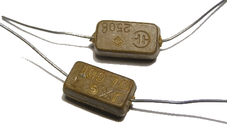
A few words about the details:
When assembling an amplifier, it is advisable to use mica capacitors as constant capacitors (in addition to electrolytic ones). For example, the CSR type, such as below in the figure.
MP40A transistors can be replaced with MP21, MP25, MP26 transistors. Transistors GT402G - on GT402V; GT404G - to GT404V;
The GT806 output transistors can be assigned any letter indices. I do not recommend using lower-frequency transistors such as P210, P216, P217 in this circuit, since at frequencies above 10 kHz they work rather poorly here (distortion is noticeable), apparently due to a lack of current amplification at high frequencies.
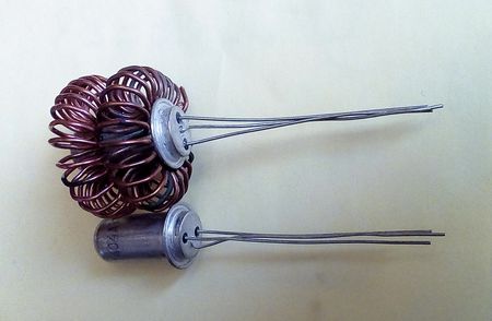
The area of radiators for output transistors must be at least 200 cm2, for pre-terminal transistors - at least 10 cm2.
For transistors of the GT402 type, it is convenient to make radiators from a copper (brass) or aluminum plate, 0.5 mm thick, 44x26.5 mm in size.

The plate is cut along the lines, then this workpiece is shaped into a tube, using for this purpose any suitable cylindrical mandrel (for example, a drill).
After this, the workpiece (1) is tightly placed on the transistor body (2) and pressed with a spring ring (3), having previously bent the side mounting ears.
The ring is made of steel wire with a diameter of 0.5-1.0 mm. Instead of a ring, you can use a copper wire bandage.
Now all that remains is to bend the side ears from below to attach the radiator to the transistor body and bend the cut feathers to the desired angle.

A similar radiator can also be made from a copper tube with a diameter of 8 mm. Cut a piece of 6...7 cm, cut the tube along the entire length on one side. Next, we cut the tube into 4 parts half the length and bend these parts in the form of petals and place them tightly on the transistor.
Since the diameter of the transistor body is about 8.2 mm, due to the slot along the entire length of the tube, it will fit tightly onto the transistor and will be held on its body due to its springy properties.
Resistors in the emitters of the output stage are either wirewound with a power of 5 W, or type MLT-2 3 Ohm, 3 pieces in parallel. I do not recommend using imported films - they burn out instantly and imperceptibly, which leads to the failure of several transistors at once.
Setting:
Setting up an amplifier correctly assembled from serviceable elements comes down to setting the quiescent current of the output stage to 100 mA using a trimming resistor (it is convenient to control the 1 Ohm emitter resistor - voltage 100 mV).
It is advisable to glue or press the VD1 diode to the heatsink of the output transistor, which promotes better thermal stabilization. However, if this is not done, the quiescent current of the output stage from cold 100mA to hot 300mA changes, in general, not catastrophically.
Important: Before turning on for the first time, you must set the trimming resistor to zero resistance.
After tuning, it is advisable to remove the trimming resistor from the circuit, measure its real resistance and replace it with a constant one.
The most scarce part for assembling an amplifier according to the above diagram is the GT806 output germanium transistors. Even in the bright Soviet times it was not so easy to acquire them, and now it is probably even more difficult. It is much easier to find germanium transistors of types P213-P217, P210.
If for some reason you cannot purchase GT806 transistors, then we offer you another amplifier circuit, where you can use the aforementioned P213-P217, P210 as output transistors.
This scheme is a modernization of the first scheme. The output power of this amplifier is 50W into a 4-ohm load and 30W into an 8-ohm load.
The supply voltage of this amplifier (U supply) is also bipolar and is ±27 V;
Operating frequency range 20Hz…20kHz:
What changes have been made to this scheme;
Added two current sources to the “voltage amplifier” and another stage to the “current amplifier”.
The use of another amplification stage on fairly high-frequency P605 transistors made it possible to somewhat unload the GT402-GT404 transistors and boost the very slow P210.
It turned out pretty good. With an input signal of 20 kHz, and with an output power of 50 W, distortion at the load is practically not noticeable (on the oscilloscope screen).
Minimal, barely noticeable distortions of the output signal shape with P210 type transistors occur only at frequencies of about 20 kHz at a power of 50 watts. At frequencies below 20 kHz and powers below 50 W, distortion is not noticeable.
In a real music signal, such powers at such high frequencies usually do not exist, so I did not notice any differences in the sound (by ear) of an amplifier with GT806 transistors and P210 transistors.
However, with transistors like GT806, if you look at it with an oscilloscope, the amplifier still works better.
With an 8 Ohm load in this amplifier, it is also possible to use output transistors P216...P217, and even P213...P215. In the latter case, the amplifier supply voltage will need to be reduced to ±23V. The output power will, of course, also drop.
Increasing the power supply leads to an increase in output power, and I think that the amplifier circuit in the second option has such potential (reserve), however, I did not tempt fate with experiments.
The following radiators are required for this amplifier - for output transistors with a dissipation area of at least 300 cm2, for pre-output P605 - at least 30 cm2, and even for GT402, GT404 (with a load resistance of 4 Ohms) are also needed.
For transistors GT402-404, you can do it easier;
Take copper wire (without insulation) with a diameter of 0.5-0.8, wind the wire turn to turn on a round mandrel (4-6 mm in diameter), bend the resulting winding into a ring (with an internal diameter less than the diameter of the transistor body), connect the ends by soldering and put the resulting “donut” on the transistor body.
It will be more efficient to wind the wire not on a round, but on a rectangular mandrel, since this increases the area of contact of the wire with the transistor body and, accordingly, increases the efficiency of heat removal.
Also, to increase the efficiency of heat removal for the entire amplifier, you can reduce the area of the radiators and use a 12V cooler from the computer for cooling, powering it with a voltage of 7...8V.
Transistors P605 can be replaced with P601...P609.
The setup of the second amplifier is similar to that described for the first circuit.
A few words about speaker systems. It is clear that to obtain good sound they must have the appropriate power. It is also advisable, using a sound generator, to go through the entire frequency range at different powers. The sound should be clear, without wheezing or rattling. Especially, as my experience has shown, this is especially true for the high-frequency speakers of speakers like S-90.
If anyone has any questions about the design and assembly of amplifiers, ask, I will try to answer if possible.
Good luck to all of you in your creativity and all the best!