The editors of the “Two Schemes” website present a simple but high-quality low-frequency amplifier based on MOSFET transistors. His circuit should be well known to radio amateurs and audiophiles, since it is already about 20 years old. The circuit was developed by the famous Anthony Holton, which is why it is sometimes called ULF Holton. The sound reinforcement system has low harmonic distortion, not exceeding 0.1%, with a load power of about 100 Watts.
This amplifier is an alternative to the popular amplifiers of the TDA series and similar pop ones, because at a slightly higher cost you can get an amplifier with clearly better characteristics.
The big advantage of the system is its simple design and output stage, consisting of 2 inexpensive MOS transistors. The amplifier can work with speakers with impedance of both 4 and 8 ohms. The only adjustment that needs to be made during startup is to set the quiescent current value of the output transistors.
Schematic diagram of UMZCH Holton
 Holton amplifier on MOSFET - circuit diagram
 The circuit is a classic two-stage amplifier; it consists of a differential input amplifier and a symmetrical power amplifier, in which one pair of power transistors operates. The system diagram is shown above.
Printed circuit board


 ULF printed circuit board - finished view
 Here is the archive with PDF files printed circuit board - .
Amplifier operating principle
Transistors T4 (BC546) and T5 (BC546) operate in a differential amplifier configuration and are designed to be powered by a current source built on the basis of transistors T7 (BC546), T10 (BC546) and resistors R18 (22 kohm), R20 (680 Ohm) and R12 (22 rooms). The input signal is fed to two filters: a low-pass filter, built from elements R6 (470 Ohm) and C6 (1 nf) - it limits the high-frequency components of the signal and a bandpass filter, consisting of C5 (1 μF), R6 and R10 (47 kohm), limiting signal components at infra-low frequencies.
The load of the differential amplifier is resistors R2 (4.7 kΩ) and R3 (4.7 kΩ). Transistors T1 (MJE350) and T2 (MJE350) represent another gain stage, and its load is transistors T8 (MJE340), T9 (MJE340) and T6 (BD139).
Capacitors C3 (33 pf) and C4 (33 pf) counteract the excitation of the amplifier. Capacitor C8 (10 nf) connected in parallel with R13 (10 kom/1 V) improves the transient response of the ULF, which is important for rapidly rising input signals.
Transistor T6, together with elements R9 (4.7 ohms), R15 (680 Ohms), R16 (82 Ohms) and PR1 (5 ohms), allows you to set the correct polarity of the amplifier output stages at rest. Using a potentiometer, it is necessary to set the quiescent current of the output transistors within 90-110 mA, which corresponds to a voltage drop across R8 (0.22 Ohm/5 W) and R17 (0.22 Ohm/5 W) within 20-25 mV. The total current consumption in idle mode of the amplifier should be around 130 mA.
The output elements of the amplifier are MOSFETs T3 (IRFP240) and T11 (IRFP9240). These transistors are installed as a voltage follower with a large maximum output current, so the first 2 stages must drive a sufficiently large amplitude for the output signal.
Resistors R8 and R17 were used mainly for quickly measuring the quiescent current of power amplifier transistors without interfering with the circuit. They may also be useful in case of expanding the system with another pair of power transistors, due to differences in resistance open channels transistors.
Resistors R5 (470 Ohm) and R19 (470 Ohm) limit the charging rate of the pass transistor capacitance, and, therefore, limit the frequency range of the amplifier. Diodes D1-D2 (BZX85-C12V) protect powerful transistors. With them, the voltage at startup relative to the power supplies of the transistors should not be more than 12 V.
The amplifier board provides space for power filter capacitors C2 (4700 µF/50 V) and C13 (4700 µF/50 V).
 Homemade transistor ULF on MOSFET
 The control is powered through an additional RC filter built on elements R1 (100 Ω/1 V), C1 (220 μF/50 V) and R23 (100 Ω/1 V) and C12 (220 μF/50 V).
Power supply for UMZCH
The amplifier circuit provides power that reaches a real 100 W (effective sine wave), with an input voltage of around 600 mV and a load resistance of 4 ohms.
 Holton amplifier on a board with details
 The recommended transformer is a 200 W toroid with a voltage of 2x24 V. After rectification and smoothing, you should get bipolar power supply to the power amplifiers in the region of +/-33 Volts. The design presented here is a mono amplifier module with very good parameters, built on MOSFET transistors, which can be used as a separate unit or as part of a .
High input impedance and shallow feedback are the main secret of warm tube sound. It's no secret that the highest quality and most expensive amplifiers, which belong to the HI-End category, are manufactured using tubes. Let's understand what a quality amplifier is? A low-frequency power amplifier has the right to be called high-quality if it completely repeats the shape of the input signal at the output without distorting it; of course, the output signal is already amplified. On the Internet you can find several circuits of really high-quality amplifiers, which can be classified as HI-End and do not necessarily require tube circuitry. For getting maximum quality, you need an amplifier whose output stage operates in pure class A. Maximum linearity of the circuit gives a minimum amount of distortion at the output, therefore, in the design of high-quality amplifiers, special attention is paid to this factor. Tube circuits are good, but not always available even for self-assembly, and industrial tube UMZCHs from branded manufacturers cost from several thousand to several tens of thousands of US dollars - this price is certainly not affordable for many.
The question arises: can similar results be achieved from transistor circuits? the answer will be at the end of the article.
There are quite a lot of linear and super-linear circuits of low-frequency power amplifiers, but the circuit that will be considered today is an ultra-linear circuit High Quality, which is implemented on only 4 transistors. The circuit was created back in 1969 by British audio engineer John Linsley-Hood. The author is the creator of several other high-quality circuits, in particular class A. Some experts call this amplifier the highest quality among transistor ULFs, and I was convinced of this a year ago.
The first version of such an amplifier was presented at. A successful attempt to implement the circuit forced me to create a two-channel ULF using the same circuit, assemble everything in a housing and use it for personal needs.
Features of the scheme
Despite its simplicity, the scheme has several features. Correct operation may be disrupted due to incorrect board layout, poor placement of components, incorrect power supply, etc.
It is the power supply that is a particularly important factor - I strongly advise against powering this amplifier from all kinds of power supplies; the best option is a battery or a power supply with a battery connected in parallel.
The amplifier power is 10 watts with a 16 Volt power supply into a 4 Ohm load. The circuit itself can be adapted for 4, 8 and 16 Ohm heads.
I created a stereo version of the amplifier, both channels are located on the same board.
The second one is intended for driving the output stage, I installed KT801 (it was quite difficult to get hold of it.
In the output stage itself, I installed powerful bipolar switches of reverse conduction - the KT803 received undoubtedly high-quality sound with them, although I experimented with many transistors - KT805, 819, 808, and even installed powerful composite switches - KT827, with it the power is much higher, but the sound is not compare with KT803, although this is just my subjective opinion.
An input capacitor with a capacity of 0.1-0.33 μF, you need to use film capacitors with minimal leakage, preferably from well-known manufacturers, the same with the output electrolytic capacitor.
If the circuit is designed for a 4 Ohm load, then you should not increase the supply voltage above 16-18 Volts.
I decided not to install a sound regulator; it, in turn, also affects the sound, but it is advisable to install a 47k resistor parallel to the input and minus.
The board itself is a prototype board. I had to tinker with the board for a long time, since the lines of the tracks also had some influence on the sound quality as a whole. This amplifier has a very wide frequency range, from 30 Hz to 1 MHz.
Setup couldn't be easier. To do this, you need to use a variable resistor to achieve half the supply voltage at the output. For more precise settings, it is worth using a multi-turn variable resistor. We connect one multimeter lead to the minus power supply, put the other one to the output line, i.e. to the plus of the electrolyte at the output, thus, slowly rotating the variable we achieve half of the power supply at the output.
There was a desire to assemble a more powerful Class A amplifier. Having read a sufficient amount of relevant literature and selected the most from what was offered latest version. It was a 30 W amplifier corresponding in its parameters to high-class amplifiers.
I did not intend to make any changes to the existing routing of the original printed circuit boards, however, due to the lack of original power transistors, a more reliable output stage was chosen using 2SA1943 and 2SC5200 transistors. The use of these transistors ultimately made it possible to provide greater output power to the amplifier. Schematic diagram my version of the amplifier below.

This is an image of boards assembled according to this circuit with Toshiba 2SA1943 and 2SC5200 transistors.

If you look closely, you can see printed circuit board Along with all the components there are bias resistors, they are 1 Watt carbon type. It turned out that they are more thermostable. When any high-power amplifier operates, a huge amount of heat is generated, so maintaining a constant rating of the electronic component when heating it is an important condition for the high-quality operation of the device.

The assembled version of the amplifier operates at a current of about 1.6 A and a voltage of 35 V. As a result, 60 W of continuous power is dissipated on the transistors in the output stage. I should note that this is only a third of the power they can handle. Try to imagine how much heat is generated on the radiators when they are heated to 40 degrees.

The amplifier case is made by hand from aluminum. Top plate and mounting plate 3mm thick. The radiator consists of two parts, its overall dimensions are 420 x 180 x 35 mm. Fasteners - screws, mostly with a countersunk stainless steel head and M5 or M3 thread. The number of capacitors was increased to six, their total capacity is 220,000 µF. A 500 W toroidal transformer was used for power supply.

Amplifier power supply
The amplifier device, which has copper busbars of the appropriate design, is clearly visible. A small toroid is added for controlled flow under the control of a DC protection circuit. There is also a high-pass filter in the power supply circuit. For all its simplicity, it must be said deceptive simplicity, the board topology of this amplifier produces sound as if without any effort, implying in turn the possibility of its infinite amplification.
Oscillograms of amplifier operation
3 dB roll-off at 208 kHz
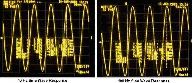
Sine wave 10 Hz and 100 Hz

Sine wave 1 kHz and 10 kHz
100 kHz and 1 MHz signals

Square wave 10 Hz and 100 Hz

Square wave 1 kHz and 10 kHz

60 W total power, 1 kHz symmetry cutoff


Thus, it becomes clear that a simple and high-quality design of UMZCH is not necessarily made using integrated circuits- only 8 transistors allow you to achieve decent sound with a circuit that can be assembled in half a day.
Scheme simple amplifier sound on transistors, which is implemented on two powerful composite transistors TIP142-TIP147 installed in the output stage, two low-power BC556B in the differential path and one BD241C in the signal pre-amplification circuit - a total of five transistors for the entire circuit! This UMZCH design can be freely used, for example, as part of a home music center or to drive a subwoofer installed in a car or at a disco.
The main attractiveness of this audio power amplifier lies in the ease of its assembly even by novice radio amateurs; there is no need for any special configuration, and there are no problems in purchasing components at an affordable price. The PA circuit presented here has electrical characteristics with high linearity of operation in frequency range from 20Hz to 20000Hz. p>
When choosing or self-production transformer for the power supply, you need to take into account the following factor: - the transformer must have a sufficient power reserve, for example: 300 W per one channel, in the case of a two-channel version, then naturally the power doubles. You can use a separate transformer for each, and if you use a stereo version of the amplifier, then you will generally get a “dual mono” type device, which will naturally increase the efficiency of sound amplification.
Effective voltage in secondary windings The transformer should be ~34v alternating, then the constant voltage after the rectifier will be in the region of 48v - 50v. In each power supply arm, it is necessary to install a fuse designed for an operating current of 6A, respectively, for stereo when operating on one power supply - 12A.
Since 08.25.2012, the Datagor whale based on the prototype discussed in the article is available!
Take it away at our Fair:
It often happens that solders turn to class “A” ultrasonic frequency circuitry in order to get to “that awesome sound,” be it the classic amplifiers of John Linsley-Hood, Nelson Pass, or many options from the Web, such as ours.
Unfortunately, not all DIYers take into account that class “A” amplifiers require the use of a power source with a very low level pulsations. And this leads to an invincible background and subsequent disappointment.
The background is an unpleasant thing, almost metaphysical. There are too many reasons and mechanisms of occurrence. There are also many methods of combating described: from correct routing of wires to changing circuits.
Today I want to address the topic of “conditioning” the ultrasonic power supply. Let's crush the pulsations!
The stereo preamplifier we bring to your attention consists of a volume control with buffer stages without common feedback on transistors that have high linearity and, according to subjective assessments, sound better than buffer stages on operational amplifiers.

It is intended for use with high-quality audio power amplifiers made using tubes, transistors or microcircuits.
Transistor symmetrical buffer stages used in the preamplifier can be used in other designs - mixers, tone blocks, correctors and other devices.
The preamplifier is made primarily of surface mount components and is the third project presented by the author in .
“It’s been a while since I picked up checkers...” Or rather, I wanted to say that I haven’t assembled transistor amplifiers for a long time. All lamps, yes lamps, you know. And then, thanks to our friendly team and participation, I purchased a couple of boards for assembly. Payments are separate.

The payments arrived quickly. Igor (Datagor) promptly sent documentation with a diagram, description of the assembly and configuration of the amplifier. The kit is good for everyone, the scheme is classic, tried and tested. But I was overcome by greed. 4.5 watts per channel will not be enough. I want at least 10 W, and not because I listen to music loudly (with my acoustics sensitivity of 90 dB and 2 W is enough), but... so that it is.

Rice. 1. Buffer assembly
Hello, friends! Have a nice summer days everyone!
I designed and tested the PCB for the buffer from my datagor article.
All parts are placed on a 55x66 mm printed circuit board made of single-sided foil fiberglass 2 mm thick.
A big hello to the Datagorians!
My first local article describes a device that allows you to determine the current gain of bipolar transistors of various powers of both structures with emitter current values from 2 mA to 950 mA.
At a certain stage of understanding the topic of amplifier construction, I realized that it is impossible to achieve high quality playback from push-pull amplifier circuits without careful selection of transistors in pairs. Push-pull initially assumes a certain degree of symmetry of the arms, and, therefore, it is worth installing transistors in the amplifier layout only after it has become known what parameters the transistors you are holding in your hands have.

This was the starting point. In addition, the authors of many circuits put forward requirements for the parameters of transistors installed in the circuit, in particular for their ability to amplify the signal.
And finally, I was interested in the problem of choosing the optimal initial current of the transistor in order to put the device in a mode that ensures maximum linearity of its operation.
Actually, the question arose: what parameters and how to measure them?
Hello, dear readers!
This small but useful addition I continue the topic raised. To avoid the need for a coupling capacitor at the output of the buffer stage, the bipolar power supply of our device is of interest (Fig. 1).

Rice. 1. Scheme of a buffer stage with bipolar power supply
For simplicity, one channel is shown and filter capacitors along the power circuits are not shown.
Offset for setting the operating mode of the buffer stage according to DC provided by a voltage source on elements HL1, R3, C2, C3, R2.
Yesterday, 17:35 changed Datagor. Companions' additions