If you need to find a malfunction of equipment or electrical wiring, one of the operations that is performed first is to test the cables and wires with a multimeter (tester) to check the serviceability of the circuit (no breaks in it), the presence of a short circuit and determine its resistance (if necessary ). In this way, it is possible to easily and quickly check the serviceability of a lamp, iron, switch, fuse, transformer. This article will discuss how to test wires correctly with a multimeter.
What you need to know about the device to connect wires
If you plan to test the wiring in your apartment, you need to know several fundamentally important facts about multimeters. First of all, it is worth noting that you can check the wire with the simplest device. An inexpensive Chinese model with minimal capabilities is quite suitable.
But at the same time, it is most convenient to use a device that has the dialing function itself. In order to set the device handle to the appropriate position, you need to turn it in the direction of the diode icon (as an option, an image of a sound wave can additionally be applied). This means that when checking the integrity of the wire when the contacts are closed, a sound will sound. sound signal.
But the presence of sound is completely optional for testing wires with a multimeter. The fact that the circuit is broken will be indicated by a unit on the display, indicating that the resistance level between the probes is higher than the measurement limit. If there is no damage in the area under study, the resistance value will be displayed on the screen, which ideally should tend to zero (subject to operation in short-distance household networks).
Sequence of actions when calling
- Before you test the circuit with a multimeter, you need to turn the handle of the device to the desired position.
- Install the ends (measuring leads) into the appropriate sockets. The black wire goes into the socket marked COM (sometimes it can be marked with “*” or a ground sign), and the red wire goes into the socket where the Ω sign is indicated (sometimes it can be marked with an R sign). It is worth noting that the Ω sign can be applied either separately or in combination with the designations of other units of measurement (V, mA). This is the correct position of the test leads, which will allow you to maintain polarity when making further measurements. Although if only the integrity of the wires is checked, their relative position will not affect the result obtained.
- Turn on the device. A separate button may be provided for this, or activation may occur automatically when the knob is turned to the desired position when selecting measurement limits or operating modes.
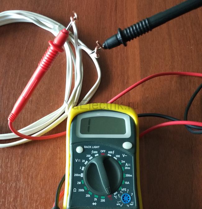
- Connect the measuring ends to each other. If a signal sounds, it means that the device is operational and ready for use.
- Take the cable or wire being tested (its ends must first be stripped of insulation, stripped to a metallic shine, and dirt and oxides removed from the surface). Touch the test leads to the exposed areas of the conductor.
- In case of continuity, a signal will sound, and the device readings will either be 0 or indicate the resistance value. If the display shows 1 and there is no beep, the tested conductor is broken.
Rules for safe calling using a multimeter

testing the network cable with a multimeter
Working with electricity does not allow for unprofessionalism, so a certain list of rules has been developed that make it possible to make it as accurate, fast and safe as possible.
- When making calls, it is most convenient to use special tips at the ends of the measuring wires, which are more commonly known as “crocodiles”. They will make the contact stable and free your hands when taking measurements.
- When testing, the circuit being tested must always be de-energized (even low-current batteries must be removed). If there are capacitors in the circuit, they must be discharged by short-circuiting. Otherwise, the device will simply burn out during work.
- Before checking the integrity of a long length of conductor when taking measurements, it is important not to touch its bare ends with your hands. This is due to the fact that the resulting readings may be incorrect.
When testing a multi-core cable, it is necessary to separate and strip all existing cores from both ends. After this, you need to check the circuit for the presence of short circuits in it: to do this, a “crocodile” is attached to each core in turn, and all the remaining ones are touched with the other measuring end in all possible combinations.
Check to see if there is a short circuit between the cable cores. If the indicator shows “1” and there is no sound signal, then everything is in order, otherwise there is a short circuit.
In this case, a sound signal will indicate the presence of a short circuit between the tested wires. This may not be of practical importance for small cross-section multi-core cables operating in low-current networks, but when working with high voltages it is fundamentally important.

We call the cable cores. There is a sound signal - everything is fine, otherwise the core is damaged.
To determine the integrity of the cores, the same operation is performed, only at one end of the cable all stripped cores are twisted together. When searching for a break, it is important to consider that the absence of a sound signal at either end will indicate a violation of the integrity of the conductor.
We check the wiring in the apartment with a multimeter
Let's take as an example a modern apartment in which the wiring is done in accordance with current requirements and standards. This means that when laying the lighting lines and power outlets, they were separated, and separate wires were laid for them in each of the rooms. Each of these circuits is powered from the apartment panel through a separate circuit breaker.
If the light has gone out in one of the rooms, you should first check that the lamp is working properly. Before starting work, it is necessary to de-energize the room/apartment depending on the power supply. When using an opaque incandescent lamp in a lamp, the integrity of the filament is difficult to visually determine, so you will need a multimeter and its continuity function. Let's figure out step by step how to do this correctly.
First you need to check the shield for triggered circuit breakers. In the first case, they will be in the on position (then the fault may be hidden in the room switch, lamp or socket). The likelihood of damage to the wiring in such a situation is low. If the device works, you will need to check everything except the room switch, including the switchboard itself.
If the machines don't work
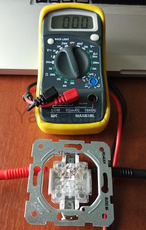
We ring the switch. When the switch is on, there should be a sound signal, when off, there should be silence and “1” on the indicator.
- Make sure there is voltage at the input and output of the machine. If it is, you can proceed to further verification.
- Prepare the device for operation and check its serviceability by short-circuiting the measuring leads.
- Unscrew the lamp from the socket.
- Touch one of the measuring probes to the base (the metal part of the lamp with threads), and the second to the central contact of the lamp (the insulated center of the end part of the base).
- A sound signal and instrument readings that are different from 0 or 1 mean that the lamp is working. If it is faulty, you need to replace it, which will solve the problem.
- We check the cartridge for serviceability. To do this, you need to disassemble the lamp, make sure that the connected wires and contacts are intact. If everything is in order, then the cause of the failure is not in the cartridge. If malfunctions are detected, they must be eliminated. The lamp cannot be screwed in yet.
- We check the serviceability of the room switch. To do this, remove the plastic cover, unscrew the screws and take it out of the mounting box. We inspect the equipment for the appearance of carbon deposits and check the tightness of the fasteners. If everything is in order, you need to install the measuring ends of the tester on the contacts of the switch. The appearance of a sound signal when dialing in the on position will indicate that the equipment is working properly. The wires do not need to be disconnected.
During such a check, as a rule, a malfunction is identified, which becomes the cause of all the troubles. Eliminating it allows you to quickly solve the problem.
If the machine worked
To ensure electrical safety during work, in this case the voltage is turned off using a general apartment circuit breaker. Next, the serviceability of the socket and the wires connected to the lamp is determined according to the algorithm described above. If there are no faults, you need to check the wiring itself using a multimeter and the continuity function. Such malfunctions happen quite rarely, but they still happen, for example, when installing suspended ceilings or decorative interior elements.
The wiring in this case is performed as follows.
- Using a screwdriver, disconnect the connected conductor (if installed correctly, it is located at the bottom) and move it to the side. The “zero” of this group is, as a rule, located at the zero clamp under the machines.
- Unscrew the incandescent lamp from the socket. Using a ready-to-use tester, we check the line by connecting one of the measuring probes to “zero” and the other to the disconnected conductor. If the device beeps, it means the wiring is shorted.
- In this case, in the room under the ceiling above the switch, we find and open the junction box. We disconnect the wires.
- We check all groups of wires for short circuits.
To determine the section of the circuit in which there is a short circuit, we again check the circuits on the apartment panel with a multimeter. If the signal sounds, it means that it is the wire laid from the switchboard to the box in the room that needs to be repaired. Otherwise, the search will need to be continued until a result is obtained.
Video
From all of the above, we can conclude that having a multimeter with a dialing function in the house is an objective necessity for any home craftsman. With such a device, in most cases it will be possible to quickly eliminate minor faults without turning to specialists for help.
This article will discuss mistakes that can be made when installing RJ45 connectors and types of damage to twisted pair cables used in data cable systems. The drawings are provided as examples of malfunctions and do not serve as examples of the correct crimping pattern.
1. Split pairs:
What is a split pair?
A split pair is a serious installation error in which wires from two different pairs are mistakenly combined into a “working” pair (the wires are not twisted together). This fault occurs when the installer confuses the same color sequence of wires in the connector at both ends of the cable. Data transmission, as before, will be carried out over two conductors, but they will no longer be twisted together.
Why is it necessary to twist wires in pairs?
In telecommunications, data is transmitted over wires twisted together - called "twisted pairs". The conductors are twisted to minimize mutual interference and reduce electromagnetic interference. Several twisted pairs in turn form a cable. Pairs even have different pitches of this twist so as to have less impact on each other. A split pair results in problems such as line crosstalk, excessive signal propagation delay between pairs, video interference, bit errors, or data loss.
Will a simple cable tester see a split pair?
Simple cable testers typically test conductors for continuity, electrical integrity, resistance, and capacitance, but do not test for crosstalk typically associated with separated pairs. Accordingly, by checking the cable with a budget twisted pair tester, you will get a good result if the line is installed incorrectly. This is because the test will be carried out only for the possibility of current flow, and since this possibility exists and the wire numbers at both ends of the cable match, the fault will not be detected. To detect split pairs you need to use a good professional cable tester. The cable length must be at least 50 cm; on shorter patch cords, it is almost impossible to detect this damage with test equipment; only visual inspection will help color scheme wires
You can detect a split pair using Softing cable testers:
2. Open pair:
.jpg) Example of pair break_1 |
 Example of pair break_2 |
A broken pair, or simply a lack of contact in a UTP, STP, FTP cable is a simple, common damage. It can be detected by any cable tester that works in tandem with a remote identifier. The device will supply a signal (current) to each conductor, and the response part will receive it. If a signal is not received from the main device, then there is no integrity of the wire. The principle of the simplest “dialing” works here. Of course, it is worth mentioning the limitations of the measuring equipment itself, which is designed for a certain maximum cable length, usually at least 305 meters, so that an entire coil of cable can be tested. The distance to a pair break can be measured by testers that can determine the line length by capacitance or by time domain reflectometry (TDR).
3. Break of one conductor (Miss wire):
.jpg) Example of a broken wire_1 |
 Example of one wire break_2 |
A broken conductor is also an easily identifiable fault. The detection methods are similar to pair breakage. It is worth noting that testers can recognize the absence of one contact as a break in the entire pair, however, this is not too important, since the line will still have to be repaired.
4. Reversed pair:
.jpg) Inverted pair example_1 |
 Example of an inverted pair_2 |
An inverted pair is an installation error of a modular connector or socket (for example RJ45). May also be called inverse or reverse. Occurs when the wires of one pair are attached to the correct contacts at one end of the cable, but are facing down at the other end. The core, which at the beginning of the line had serial No. 3 (Fig. Example of an inverted pair_1), at the end of the cable is crimped onto contact No. 6, and No. 6, in turn, comes to contact No. 3. This damage can be detected by any tester, but it can only be localized by visually inspecting the connector.
5. Crossed wires:
.jpg) Example of crossed wires_1 |
 Example of crossed wires_2 |
The “crossed wires” twisted pair installation error occurs when the installer, having crimped the connector correctly on one side of the cable, swapped wires from different pairs on the other end. The problem is easily identified even by simple testers. This can be solved by repeated, more careful crimping of the connector in compliance with the correct crimping pattern.
During installation and repair computer networks and communications, there is often a need to check the integrity of the twisted pair, the absence of short circuits, the correct crimping, and so on.
Of course, if you have the appropriate equipment (for example, a LAN tester or at least a multimeter), this task comes down to simply connecting a cable to the appropriate device and checking it using standard methods.
But the required device is not always at hand. Sometimes you need to check twisted pair at home, so to speak “on the knee”.
Method 1. Checking the twisted pair with a multimeter.
I think that many people at home or in the garage have a multimeter, dial tester or similar device for measuring resistance, voltage and current in a circuit.
With this device you can very easily and quickly check a twisted pair cable for breaks, short circuits and overall performance.
The twisted pair is checked with a device operating in resistance measurement mode.
If it is possible to bring the ends of the cable to one point, then the test will be performed as follows - first, we will check the integrity of each core separately, for this we will test each cable one by one by color. Then we’ll check for a short circuit with other cores - to do this, touch one wire on one connector, and touch each one in turn on the opposite connector. Resistance should be shown only in cases where there is contact between the probes (in the first case, it indicates that the wire is in order, in the second, that there is a short circuit with the corresponding wire).
However, it is not always possible to bring both ends of the cable together at one point, so you can use the following trick: either cut off the connector, strip the wires at one end and connect them in pairs, each pair with each other. After this, test each pair at the other end with a multimeter. If you have time and desire, you can take the old one computer socket with a working connector and close the contacts inside it, this will make it possible not to cut the connector or strip the wires. Additionally, you can not only short-circuit the contacts inside the socket, but also connect them using resistors with different resistance values - then you can see if there is a short circuit between the pairs. (The resistance on the multimeter will correspond to the resistor value + a slight increase due to the length of the wire).
Method 2. Checking twisted pair cables without a multimeter.
If you don’t have a multimeter, but you still need to check the cable, then you can use the “old-fashioned” method: At one end, the wires are stripped to a length of about 5 centimeters and lowered into a glass of warm, highly salted water.
After this, at the other end of the cable, a voltage of more than 3 V is applied to one of the pairs. To do this, you can use a Krona battery, a battery from cell phone, battery from the motherboard. If you don’t have any of the listed power sources at hand, you can use a standard AA battery at 1.5V, but then the water must be heavily salted.
The container with water must be made of dielectric (plastic, glass).
After power is applied, the following will happen inside the glass: white hydrogen bubbles will be actively released at the cathode (negative pole), while yellow chlorine bubbles will also be actively released at the anode (positive pole). This means that the wires are in good condition, they conduct current and there is no short circuit between them.
Another original way to check is to insert one pair into the potatoes to a depth of 1-1.5 cm. And apply food in the same way as described above. After this, white bubbles should appear on the cathode, and the area around the anode connection will turn green.
In fact, there are a huge number of these “folk” methods for checking different cables. It would be interesting to know what methods you use, which ones you have heard of, etc.
If a PC owner encounters problems with the Internet and, when trying to connect to the network, sees the error “network cable not connected,” then most likely there are problems that will be quite difficult to fix on your own. A more reliable sign of cable damage is the absence of an LED signal at the input point of the Internet plug. Unfortunately not all motherboards have a light indicating that a working wire is connected. This is also true for external network cards inserted into the PCE slot that do not have LED indicators.
You can try to solve this problem on your own. To do this, you need to determine what exactly caused the lack of Internet. Here are some of the most common problems that you can fix yourself:
- Unstable mains voltage. This problem leads to many malfunctions in the computer, one of which is problems with the Internet. The solution to the problem is to install uninterruptible source power supply that protects against voltage surges.
- Use of unlicensed software. One of the most common sources of problems when operating a PC is the use of unverified programs that can lead to errors or contain malware. Therefore, on computers used for work and containing important data, only licensed software should be used.
- Network equipment is turned off. Sometimes internet problems can be caused by something as simple as a disabled network adapter. To check activity of this device, you need to go to the “Control Panel” in Windows, find the item “ Network connections", go into it and select the "Network adapters" tab. In the window that opens, make sure the adapter is active.
- There are no drivers for network equipment. This problem especially relevant when reinstalling operating system. To make sure you have the correct drivers network equipment, you need to go to the “Control Panel” tab, select “System”, open the “Device Manager” menu, find “ Network adapter» and see its properties. If there are no warning error messages, then the problem is most likely not with the drivers.
All of the above errors can usually be resolved through the efforts of the computer owner.
Help from specialists
If the above-described causes of the malfunction do not apply or you cannot cope with the problem yourself, then you should use the help of professionals. The first thing you need to do if you have problems with the Internet or the power cord is to call the operator of the provider that provides network access services. Thanks to this, you can quickly find out if there is cable damage or any other breakdowns.
If, after calling the operator, the computer owner found out that there was no problem on the operator’s part, and also checked his PC for serviceability, then we can say that the cable is damaged. You can fix the problem by using the services of specialists from a company that provides Internet access.
In some cases, you can try to fix wire damage yourself. To do this you need to know possible types breakdowns and ways to eliminate them. The most common malfunctions that appear due to mechanical damage to the cable are the following:
- The most common reason is a complete cable break. It usually occurs due to negative mechanical effects, such as overstraining or operation at temperatures exceeding the norm for a cable of this type.
- Short circuit between twisted pair wires. This is also a fairly common cause of problems with the Internet. Also appears due to pressure and impacts.
If you find a cable break, you can try to fix the problem yourself. It is also quite easy to check for functionality network card, which also often causes network problems. To do this, just install it in another computer and connect the Internet cable. But this opportunity is relevant if you have access to the network through a working wire.
To accurately determine whether an Internet cable is faulty, you must have knowledge of correct connection wires through a switch, hub or other devices, as well as have a general knowledge of the principle of transmitting information through twisted pair.
It is also advisable to familiarize yourself with the cable connection diagram. Basically, for wires transmitting any digital data, a transformer connection circuit is used to avoid interference. Thanks to the knowledge of the above-described causes of cable failure, anyone can eliminate the fault or broken conductor.