As many PC users as there are in the world, almost as many computers sooner or later fail to start for various reasons. If you have a speaker in your case, then, as a rule, when the system starts successfully, a single short signal is heard. However, if you hear any other sequence of beeps when you start your computer, then this manual will help you figure out what the problem is.
How it works
When you turn on the computer, programs that are part of the BIOS (basic input/output system) of the motherboard perform self-tests hardware PC. This self-test is called POST (Power-On Self-Test).
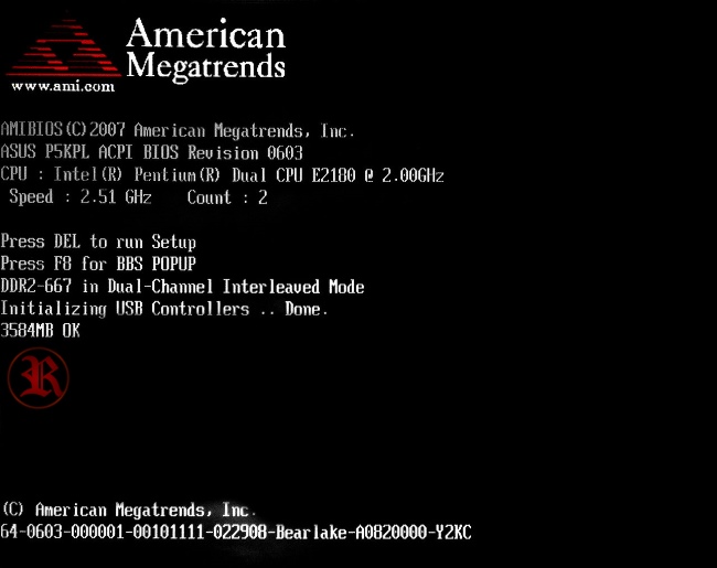
POST screen
While the POST screen is displayed on the monitor, the BIOS utilities check all components step by step. As soon as a problem is detected, for example, with RAM or a video card, the BIOS sends a signal to the speaker connected in the case, and the latter produces a sequence of error signals.

Speaker
If there is no speaker in the PC case, then you will not be able to find out the error code by sound signal in any other way!
In addition, you need to know exactly the manufacturer and version Motherboard BIOS fees, because codes sound errors(beep codes) may differ for each BIOS.
Sound table
AMI BIOS (American Megatrends, Inc.)
| Description of the error | |
|---|---|
| 1 short | |
| 2 short | RAM parity error or scanner or printer not turned off |
| 3 short | Error in the first 64 KB of RAM |
| 4 short | The system timer is faulty. Replace the motherboard. |
| 5 short | Processor problems |
| 6 short | |
| 7 short | Problems with the motherboard |
| 8 short | Video card memory error |
| 9 short | BIOS checksum is incorrect |
| 10 short | CMOS write error |
| 11 short | Error in the cache located on the motherboard |
| 1 long, 1 short | Problems with the power supply |
| 1 long, 2 short | |
| 1 long, 3 short | Video card error (Mono-CGA). Malfunction of connectors random access memory. Replace the motherboard. |
| 1 long, 4 short | No video card |
| 1 long, 8 short | Problems with the video card or the monitor is not connected |
| 3 long | RAM - Read/Write test completed with error. Reinstall the memory or replace it with a working module. |
| 5 short, 1 long | RAM is not installed or is not installed as recommended by the motherboard manufacturer |
| Continuous beep | The power supply is faulty or the computer is overheating |
Award BIOS
| Sequence of beeps | Description of the error |
|---|---|
| 1 short | Successful POST: no errors detected, computer is working properly |
| 2 short |
Minor errors found. |
| 3 long | Keyboard controller initialization error |
| 1 short, 1 long | Random access memory (RAM) error |
| 1 long, 2 short | Video card error |
| 1 long, 3 short | No video card or video memory error |
| 1 long, 9 short | Error reading from ROM |
| Repeating short |
Problems with the power supply or RAM |
| Repeating long | RAM problems |
| Repeating with high-low frequency | CPU problems |
| Continuous | Problems with the power supply |
IBM BIOS
| Sequence of beeps | Description of the error |
|---|---|
| 1 short | Successful POST: no errors detected, computer is working properly |
| 1 beep and blank screen | Video system is faulty |
| 2 short | Video system is faulty |
| 3 long | Faulty motherboard(keyboard controller error), poor or missing connection to the RAM stick |
| 1 long, 1 short | Motherboard is faulty |
| 1 long, 2 short | Video system faulty (Mono/CGA) |
| 1 long, 3 short | Video system (EGA/VGA) is faulty |
| Repeating short | Malfunctions related to the power supply or motherboard |
| Continuous | Problems with the power supply or motherboard |
| Absent | Faulty power supply, motherboard, speaker, or no power to CPU |
Quadtel BIOS
Compaq BIOS
| Sequence of beeps | Description of the error |
|---|---|
| 1 short | Successful POST: no errors detected, computer is working properly |
| 1 long, 1 short | BIOS CMOS memory checksum error. The ROM battery may have run out. |
| 2 short | Global error |
| 1 long, 2 short | Error initializing video card. Check that the video card is installed correctly. |
| 7 beeps (1 long, 1 s, 1?, 1 short, pause, 1 long, 1 short, 1 short) | AGP video card malfunction. Check that the installation is correct. |
| 1 long constant | RAM error. Try rebooting. |
| 1 short, 2 long | RAM malfunction. Reboot via Reset. |
AST BIOS
| Sequence of beeps | Description of the error |
|---|---|
| 1 short | Error when checking processor registers. Processor malfunction. |
| 2 short | Keyboard controller buffer error. Keyboard controller malfunction. |
| 3 short | Keyboard controller reset error. The keyboard controller is faulty or motherboard. |
| 4 short | Keyboard communication error |
| 5 short | Keyboard error |
| 6 short | System board error |
| 9 short | BIOS ROM checksum mismatch. The BIOS ROM chip is faulty. |
| 10 short | System timer error. The system timer chip is faulty. |
| 11 short | Chip error system logic(chipset) |
| 12 short | Power management register error in non-volatile memory |
| 1 long | DMA controller error 0. The channel 0 DMA controller chip is faulty. |
| 1 long, 1 short | DMA controller error 1. The channel 1 DMA controller chip is faulty. |
| 1 long, 2 short | Frame retrace suppression error. The video card may be faulty. |
| 1 long, 3 short | Error in video memory. The video card memory is faulty. |
| 1 long, 4 short | Video adapter error. The video card is faulty. |
| 1 long, 5 short | Memory error 64K |
| 1 long, 6 short | Failed to load interrupt vectors. The BIOS was unable to load interrupt vectors into memory. |
| 1 long, 7 short | Failed to initialize video subsystem |
| 1 long, 8 short | Video memory error |
In DELL BIOS and Phoenix BIOS, which are presented below, Beep codes are arranged in a sequence of sound signals. Let's say 1-1-2 means 1 beep, pause, 1 beep, pause, and 2 beeps.
DELL BIOS
Phoenix BIOS
| Sequence of beeps | Description of the error |
|---|---|
| 1-1-2 | Error during processor test. The processor is faulty. Replace the processor. |
| 1-1-3 | Error writing/reading data to/from CMOS memory |
| 1-1-4 | An error was detected when calculating the checksum of the BIOS contents |
| 1-2-1 | |
| 1-2-2 or 1-2-3 | DMA controller initialization error |
| 1-3-1 | Error initializing the RAM regeneration circuit |
| 1-3-3 or 1-3-4 | Error initializing the first 64 KB of RAM |
| 1-4-1 | Motherboard initialization error |
| 1-4-2 | |
| 1-4-3 | |
| 1-4-4 | Error writing/reading to/from one of the I/O ports |
| 2-1-1 | An error was detected when reading/writing bit 0 (in hexadecimal) of the first 64 KB of RAM |
| 2-1-2 | An error was detected when reading/writing the 1st bit (in hexadecimal) of the first 64 KB of RAM |
| 2-1-3 | An error was detected when reading/writing the 2nd bit (in hexadecimal) of the first 64 KB of RAM |
| 2-1-4 | An error was detected when reading/writing the 3rd bit (in hexadecimal) of the first 64 KB of RAM |
| 2-2-1 | An error was detected when reading/writing the 4th bit (in hexadecimal) of the first 64 KB of RAM |
| 2-2-2 | An error was detected when reading/writing the 5th bit (in hexadecimal) of the first 64 KB of RAM |
| 2-2-3 | An error was detected when reading/writing the 6th bit (in hexadecimal) of the first 64 KB of RAM |
| 2-2-4 | An error was detected when reading/writing the 7th bit (in hexadecimal) of the first 64 KB of RAM |
| 2-3-1 | An error was detected when reading/writing the 8th bit (in hexadecimal) of the first 64 KB of RAM |
| 2-3-2 | An error was detected when reading/writing the 9th bit (in hexadecimal) of the first 64 KB of RAM |
| 2-3-3 | An error was detected when reading/writing the 10th bit (in hexadecimal) of the first 64 KB of RAM |
| 2-3-4 | An error was detected when reading/writing the 11th bit (in hexadecimal) of the first 64 KB of RAM |
| 2-4-1 | An error was detected when reading/writing the 12th bit (in hexadecimal) of the first 64 KB of RAM |
| 2-4-2 | An error was detected when reading/writing the 13th bit (in hexadecimal) of the first 64 KB of RAM |
| 2-4-3 | An error was detected when reading/writing the 14th bit (in hexadecimal) of the first 64 KB of RAM |
| 2-4-4 | An error was detected when reading/writing the 15th bit (in hexadecimal) of the first 64 KB of RAM |
| 3-1-1 | Error initializing the second DMA channel |
| 3-1-2 or 3-1-4 | Error initializing the first DMA channel |
| 3-2-4 | Keyboard controller initialization error |
| 3-3-4 | Video memory initialization error |
| 3-4-1 | Serious problems occurred when trying to access the monitor |
| 3-4-2 | Cannot initialize video card BIOS |
| 4-2-1 | System timer initialization error |
| 4-2-2 | Testing completed |
| 4-2-3 | Keyboard controller initialization error |
| 4-2-4 | Critical error when the CPU enters protected mode |
| 4-3-1 | Error initializing RAM |
| 4-3-2 | Error initializing first timer |
| 4-3-3 | Error initializing second timer |
| 4-4-1 | Error initializing one of the serial ports |
| 4-4-2 | Parallel port initialization error |
| 4-4-3 | Math coprocessor initialization error |
| Long, continuous beeps | Motherboard is faulty |
| Siren sound from high to low frequency | The video card is faulty, check the electrolytic capacitors for leaks or replace everything with new ones that are known to be good |
| Continuous signal | CPU cooler not connected (defective) |
The article will be supplemented as necessary.
BIOS signal tables are taken from Wikipedia.
Description:
I bring to your attention the main POST codes forBIOSmanufacturerAMI. A short introduction. Immediately after pressing the POWER button on system unit personal computer PC control goes directly to the BIOS. At this time (at the beginning of the PC startup), the processor sends a signal to the BIOS chip, which initializes the loading of the BOOT-ROUTINE firmware of the Basic I/O System.
The BOOT-ROUTINE firmware calls the POST self-test routine.
Subroutine POST (Power-On Self Test) tests the equipment installed on the computer, configures it and prepares it for work.
A separate test is performed for each individual piece of equipment (processor, memory, video card, keyboard, input/output ports, etc.). Each test has its own unique number, which is called a POST code. POST code written to the Manufacturing Test Port (with address 0080H) before running each individual POST test.
After the POST test code is written to the Manufacturing Test Port, the testing procedure for the corresponding equipment begins. If the testing procedure fails, the POST code of the last procedure (which caused the error) remains in the Manufacturing Test Port. If you know the POST code of the last procedure, you can determine the device that caused the error.
Reading POST codes can be done in several ways.
- If your motherboard has a built-in POST code indicator, information about the POST code of the last procedure can be found from it.
- On some systems, the POST code of the last procedure performed may be displayed on the monitor screen during the POST procedure.
- A special expansion card can be used to read POST codes.
Since BIOS is produced by several manufacturers, each BIOS from an individual manufacturer has its own table of POST codes.
This table contains POST codes that are displayed during the full POST procedure.
- CF Detects processor type and tests CMOS read/write
- C0 The chipset and L1-, L2-cache are pre-initialized, the interrupt controller, DMA, timer are programmed
- C1 The type and amount of RAM is detected
- C3 BIOS code is unpacked into a temporary area of RAM
- 0C BIOS checksums are checked
- C5 BIOS code is copied to shadow memory and control is transferred to the Boot Block module
- 01 XGROUP module is unpacked at physical address 1000:0000h
- 02 Processor initialization. The CR and MSR registers are set
- 03 I/O resources are determined (Super I/O)
- 05 Clears screen and CMOS status flag
- 06 Coprocessor is being checked
- 07 Keyboard controller is identified and tested
- 08 Keyboard interface is detected
- 09 Initializing the Serial ATA controller
- OA Detects the keyboard and mouse that are connected to the PS/2 ports
- 0B AC97 audio controller resources are being installed
- OE Testing memory segment F000h
- 10 The type of flash memory is determined
- 12 CMOS tested
- 14 Sets values for chipset registers
- 16 The clock generator is initially initialized
- 18 The processor type, its parameters and L1 and L2 cache sizes are determined
- 1B The interrupt vector table is initialized
- 1C Checks CMOS checksums and battery voltage
- 1D Power management system is defined
- 1F Loads the keyboard matrix (for laptops)
- 21 The Hardware Power Management system is initializing (for laptops)
- 23 Math coprocessor, disk drive, chipset initialization are tested
- 24 The processor microcode is being updated. Creates a resource distribution map for Plug and Play devices
- 25 Initial PCI initialization: lists devices, searches for VGA adapter, writes VGA BIOS to C000:0
- 26 Installed clock frequency by CMOS Setup. Synchronization of unused DIMM and PCI slots is disabled. The monitoring system (H/W Monitor) is initialized
- 27 Interrupt INT 09h enabled. The keyboard controller is initialized again
- 29 MTRR registers are programmed, APIC is initialized. The IDE controller is being programmed. The processor frequency is measured. The video system BIOS extension is called
- 2B Search for video adapter BIOS
- 2D The Award splash screen is displayed, information about the processor type and its speed
- 33 Keyboard reset
- 35 First DMA channel being tested
- 37 Second DMA channel being tested
- 39 DMA page registers are tested
- 3C Configuring 8254 controller (timer)
- 3E Checking the 8259 interrupt controller
- 43 Interrupt controller is checked
- 47 ISA/EISA buses are tested
- 49 The amount of RAM is calculated. Registers are configured for AMD processor K5
- 4E MTRR registers are programmed for Syrix processors. L2 cache and APIC are initialized
- 50 USB bus detected
- 52 The RAM is tested and the results are displayed. Clearing extended memory
- 53 If the CMOS is cleared, the login password is reset
- 55 Displays the number of processors (for multiprocessor platforms)
- 57 The EPA logo is displayed. Initial Initialization of ISA PnP Devices
- 59 Virus protection system is determined
- 5B Display prompt for startup BIOS updates from a floppy disk
- 5D Launches Super I/O controller and integrated audio controller
- 60 Entering CMOS Setup if the Delete key was pressed
- 65 PS/2 mouse is initializing
- 69 L2 cache enabled
- 6B Chipset registers are configured according to BIOS Setup
- 6D Assigns resources for ISA PnP devices and COM ports for integrated devices
- 6F Initializes and configures the floppy disk controller
- 75 IDE devices are detected and installed: hard disks, CD/DVD, LS-120, ZIP, etc.
- 76 Information about detected IDE devices is displayed
- 77 Serial and parallel ports are initialized
- 7A The math coprocessor is reset and ready for operation.
- 7C Defines protection against unauthorized writing to hard drives
- 7F If there are errors, a message is displayed and the Delete and F1 keys are pressed
- 82 Memory is allocated for power management and changes are written to the ESCD table.
- The splash screen with the EPA logo is removed. Requests a password if needed
- 83 All data is saved from the temporary stack to CMOS
- 84 Displaying Initializing Plug and Play Cards message
- 85 USB initialization complete
- 87 SYSID tables are created in the DMI area
- 89 ACPI tables are being installed. Interrupts are assigned to PCI devices
- 8B Called by the BIOS of additional ISA or PCI controllers, with the exception of the video adapter
- 8D Sets RAM parity parameters using CMOS Setup. APM is initialized
- 8F IRQ 12 is allowed for hot plugging of a PS/2 mouse
- 94 Completion of chipset initialization. Displays the resource allocation table. Enable L2 cache. Setting the summer/winter time transition mode
- 95 Sets the keyboard auto-repeat frequency and Num Lock state
- 96 For multiprocessor systems, registers are configured (for Cyrix processors). The ESCD table is created. The DOS Time timer is set according to the RTC CMOS clock. Boot device partitions are saved for use by the built-in antivirus. The speaker announces the end of POST. The MSIRQ FF table is created. The BIOS INT 19h interrupt is executed. Search for the bootloader in the first sector of the boot device
A shortened procedure is performed by setting the Quick Power On Self Test option in the BIOS.
- 65 The video adapter is being reset. The sound controller and input/output devices are initialized, the keyboard and mouse are tested. BIOS integrity is checked
- 66 Cache is initializing. An interrupt vector table is created. The power management system is initializing
- 67 The CMOS checksum is checked and the battery is tested. The chipset is configured based on CMOS parameters
- 68 Video adapter is initializing
- 69 Configuring the interrupt controller
- 6A Testing RAM (accelerated)
- 6B Displays EPA logo, CPU and memory test results
- 70 A prompt to enter BIOS Setup is displayed. A mouse connected to PS/2 or USB is initialized
- 71 Cache controller is initializing
- 72 Chipset registers are being configured. A list of Plug and Play devices is created.& The drive controller is initialized
- 73 Hard disk controller is initializing
- 74 Coprocessor is initializing
- 75 If necessary, HDD write protected
- 77 If necessary, a password is requested and messages Press F1 to continue, DEL to enter Setup are displayed
- 78 Expansion cards with their own BIOS are initialized
- 79 Platform resources are initializing
- 7A The root table RSDT, device tables DSDT, FADT, etc. are generated.
- 7D Collects information about boot device partitions
- 7E BIOS is preparing to boot operating system
- 7F The NumLock indicator status is set according to the settings
- BIOS Setup
- 80 INT 19 is called and the operating system starts
AMIBIOS8.0
- D0 Initialization of the processor and chipset. Verifying BIOS boot block checksums
- D1 Initialization of I/O ports. The command for the BAT self-test is sent to the keyboard controller
- D2 Disable L1/L2 cache. The amount of installed RAM is determined
- D3 Memory regeneration schemes are configured. Allowed to use cache memory
- D4 Test 512 KB memory. The stack is installed and the communication protocol with the cache memory is assigned
- D5 BIOS code is unpacked and copied to shadow memory
- D6 Checks BIOS checksums and pressing Ctrl+Home keys (BIOS recovery)
- D7 Control is transferred to the interface module, which unpacks the code into the Run-Time area
- D8 The executable code is unpacked from flash memory into operational memory. CPUID information is saved
- D9 The unpacked code is transferred from the temporary storage area to segments 0E000h and 0F000h of RAM
- DA CPUID registers are restored. POST execution is moved to RAM
- E1–E8, EC–EE Errors related to the system memory configuration
- 03 Processing of NMI, parity errors, and output of signals to the monitor is prohibited. An area is reserved for the GPNV event log, the initial values of variables from the BIOS are set
- 04 Checks battery health and calculates CMOS checksum
- 05 The interrupt controller is initialized and the vector table is built
- 06 The timer is being tested and prepared for operation
- 08 Keyboard testing (keyboard lights flashing)
- C0 Initial processor initialization. Do not use cache memory. Defined by APIC
- C1 For multiprocessor systems, the processor responsible for starting the system is determined
- C2 Completes the assignment of the processor to start the system. Identification using CPUID
- C5 The number of processors is determined and their parameters are configured
- C6 Initializes cache memory for faster POST.
- C7 Processor initialization completes
- 0A Keyboard controller detected
- 0B Search for a mouse connected to the PS/2 port
- 0C Checking for keyboard presence
- 0E Detected and initialized various devices input
- 13 Initial initialization of chipset registers
- 24 Platform-specific BIOS modules are unpacked and initialized.
- An interrupt vector table is created and interrupt processing is initialized.
- 2A The DIM mechanism identifies devices on local buses. The video adapter is being prepared for initialization, a resource distribution table is being built
- 2C Detection and initialization of the video adapter, the video adapter is called by the BIOS
- 2E Finding and initializing additional I/O devices
- 30 Prepares for SMI processing
- 31 ADM module is initialized and activated
- 33 The simplified loading module is initializing
- 37 Displays AMI logo, BIOS version, processor version, key prompt to enter BIOS
- 38 Using DIM, various devices on local buses are initialized
- 39 DMA controller is initializing
- 3A Sets the system time according to the RTC clock
- 3B RAM is tested and results are displayed
- 3C Chipset registers are configured
- 40 Serial and parallel ports, mathematical coprocessor, etc. are initialized.
- 52 Based on the results of the memory test, the RAM data in CMOS is updated
- 60 In BIOS Setup, the NumLock state is set and auto-repeat parameters are configured
- 75 The procedure for working with disk devices(interrupt INT 13h)
- 78 A list of IPL devices is created (from which the operating system can be loaded)
- 7C ESCD extended system configuration tables are created and written to NVRAM
- 84 Log errors encountered during POST
- 85 Messages are displayed about detected non-critical errors.
- 87 If necessary, BIOS Setup is launched, which is first unpacked into RAM
- 8C Chipset registers are configured in accordance with BIOS Setup
- 8D ACPI tables are built
- 8E Configures non-maskable interrupt (NMI) service
- 90 SMI is finally initialized
- A1 Clearing data that is not needed when loading the operating system
- A2 EFI modules are prepared to interact with the operating system
- A4 In accordance with the BIOS Setup language module is initialized
- A7 The POST procedure summary table is displayed
- A8 Sets the state of the MTRR registers
- A9 If necessary, waits for keyboard commands to be entered
- AA Removes POST interrupt vectors (INT 1Ch and INT 09h)
- AB Devices for loading the operating system are detected
- AC The final stages of setting up the chipset in accordance with BIOS Setup
- B1 ACPI interface is configured
- 00 Interrupt processing INT 19h is called (boot sector search, OS loading)
Phoenix Bios 4.0
- 02 Verify Real Mode
- 03 Disable Non-Maskable Interrupt (NMI)
- 04 Get CPU type
- 06 Initialize system hardware
- 08 Initialize chipset with initial POST values
- 09 Set IN POST flag
- 0A Initialize CPU registers
- 0B Enable CPU cache
- 0C Initialize caches to initial POST values
- 0E Initialize I/O component
- 0F Initialize the local bus IDE
- 10 Initialize Power Management
- 11 Load alternate registers with initial POST values
- 12 Restore CPU control word during warm boot
- 13 Initialize PCI Bus Mastering devices
- 14 Initialize keyboard controller
- 16 (1-2-2-3) BIOS ROM checksum
- 17 Initialize cache before memory autosize
- 18 8254 timer initialization
- 1A 8237 DMA controller initialization
- 1C Reset Programmable Interrupt Controller
- 20 (1-3-1-1) Test DRAM refresh
- 22 (1-3-1-3) Test 8742 Keyboard Controller
- 24 Set ES segment register to 4 GB
- 26 Enable A20 line
- 28 Autosize DRAM
- 29 Initialize POST Memory Manager
- 2A Clear 512 KB base RAM
- 2C (1-3-4-1) RAM failure on address line xxxx
- 2E (1-3-4-3) RAM failure on data bits xxxx of low byte of memory bus
- 2F Enable cache before system BIOS shadow
- 30 (1-4-1-1) RAM failure on data bits xxxx of high byte of memory bus
- 32 Test CPU bus-clock frequency
- 33 Initialize Phoenix Dispatch Manager
- 34 Disable Power Button during POST
- 35 Re-initialize registers
- 36 Warm start shut down
- 37 Re-initialize chipset
- 38 Shadow system BIOS ROM
- 39 Re-initialize cache
- 3A Autosize cache
- 3C Advanced configuration of chipset registers
- 3D Load alternate registers with CMOS values
- 40 CPU speed detection
- 42 Initialize interrupt vectors
- 45 POST device initialization
- 46 (2-1-2-3) Check ROM copyright notice
- 48 Check video configuration against CMOS
- 49 Initialize PCI bus and devices
- 4A Initialize all video adapters in system
- 4B QuietBoot start (optional)
- 4C Shadow video BIOS ROM
- 4E Display BIOS copyright notice
- 50 Display CPU type and speed
- 51 Initialize EISA board
- 52 Test keyboard The keyboard is being tested
- 54 Set key click if enabled
- 55 Initialize USB bus
- 58 (2-2-3-1) Test for unexpected interrupts
- 59 Initialize POST display service
- 5A Display prompt “Press F2 to enter SETUP”
- 5B Disable CPU cache
- 5C Test RAM between 512 and 640 KB
- 60 Test extended memory
- 62 Test extended memory address lines
- 64 Jump to UserPatch1
- 66 Configure advanced cache registers
- 67 Initialize Multi Processor APIC
- 68 Enable external and CPU caches
- 69 Setup System Management Mode (SMM) area
- 6A Display external L2 cache size
- 6B Load custom defaults (optional)
- 6C Display shadow-area message
- 6E Display possible high address for UMB recovery
- 70 Display error messages Error messages are displayed
- 72 Check for configuration errors
- 76 Check for keyboard errors
- 7C Set up hardware interrupt vectors
- 7D Initialize hardware monitoring
- 7E Initialize coprocessor if present
- 80 Disable onboard Super I/O ports and IRQs
- 81 Late POST device initialization
- 82 Detect and install external RS232 ports
- 83 Configure non-MCD IDE controllers
- 84 Detect and install external parallel ports
- 85 Initialize PC-compatible PnP ISA devices
- 86 Re-initialize onboard I/O ports
- 87 Configure Motheboard Configurable Devices (optional)
- 88 Initialize BIOS Data Area
- 89 Enable Non-Maskable Interrupts (NMIs)
- 8A Initialize Extended BIOS Data Area
- 8B Test and initialize PS/2 mouse
- 8C Initialize floppy controller
- 8F Determine number of ATA drives (optional)
- 90 Initialize hard-disk controllers
- 91 Initialize local-bus harddisk controllers
- 92 Jump to UserPatch2
- 93 Build MPTABLE for multi-processor boards
- 95 Install CD ROM for boot
- 96 Clear huge ES segment register
- 97 Fixup Multi Processor table
- 98 (1-2) Search for option ROMs. One long, two short beeps on checksum failure
- 99 Check for SMART Drive (optional)
- 9A Shadow option ROMs
- 9C Set up Power Management
- 9D Initialize security engine (optional)
- 9E Enable hardware interrupts
- 9F Determine number of ATA and SCSI drives
- A0 Set time of day
- A2 Check key lock
- A4 Initialize Typical rate
- A8 Erase F2 prompt
- AA Scan for F2 key stroke
- AC Enter SETUP
- AE Clear Boot flag
- B0 Check for errors
- B2 POST done – prepare to boot operating system
- B4 (1) One short beep before boot
- B5 Terminate QuietBoot (optional)
- B6 Check password (optional)
- B9 Prepare Boot
- BA Initialize DMI parameters
- BB Initialize PnP Option ROMs
- BC Clear parity checkers
- BD Display MultiBoot menu
- BE Clear screen (optional)
- BF Check virus and backup reminders
- C0 Try to boot with INT 19
- C1 Initialize POST Error Manager (PEM)
- C2 Initialize error logging
- C3 Initialize error display function
- C4 Initialize system error handler
- C5 PnPnd dual CMOS (optional)
- C6 Initialize notebook docking (optional)
- C7 Initialize notebook docking late
- D2 Unknown interrupt
- E0 Initialize the chipset
- E1 Initialize the bridge
- E2 Initialize the CPU
- E3 Initialize system timer
- E4 Initialize system I/O
- E5 Check force recovery boot
- E6 Checksum BIOS ROM
- E7 Go to BIOS
- E8 Set Huge Segment
- E9 Initialize Multi Processor
- EA Initialize OEM special code
- EB Initialize PIC and DMA
- EC Initialize Memory type
- ED Initialize Memory size
- EE Shadow Boot Block
- EF System memory test
- F0 Initialize interrupt vectors
- F1 Initialize Real Time Clock
- F2 Initialize video
- F3 Initialize System Management Mode
- F4 (1) Output one beep before boot
- F5 Boot to Mini DOS
- F6 Clear Huge Segment
- F7 Boot to Full DOS
Original and reliable tables of POST codes can be found on the corresponding websites of BIOS manufacturers: “AMI” and “Award”. Sometimes POST code tables are provided in motherboard manuals.
1. Test of software-accessible processor registers (POST codes: 01, 02).
2. Checking the RAM regeneration period (POST code: 04).
3. Initialize the keyboard controller (POST code: 05).
4. Preliminary check of the performance of non-volatile memory (CMOS) and the condition of the CMOS battery (POST code: 07).
5. Initialization of chipset registers with default values (POST code: BE, hex).
6. Checking the presence and determining the size of RAM (POST code: C1, hex).
7. Determining the presence and size of external cache memory (POST code: C6, hex).
8. Checking the first 64 KB of RAM (POST code: 08).
9. Initialization of interrupt vectors (POST code: 0A, hex).
10. Checking the CMOS checksum (POST code: 0V, hex).
11. Detection and initialization of the video controller (POST code: 0D, hex).
12. Video memory check (POST code: 0E, hex).
13. Checking the BIOS checksum (POST code: 0F, hex).
14. Checking controllers and DMA page registers (POST codes: 10,
11, hex).
15. Checking the system timer (POST code: 14, hex).
16. Checking and initializing interrupt controllers (POST codes: 15...18, hex).
17. Initialization of expansion bus slots (POST codes: 20…2F, hex).
18. Determining the size and checking the main and extended memory (POST codes: 30, 31, hex).
19. Re-initialize the chipset registers in accordance with the values set in CMOS Setup (POST code: BF, hex).
20. Initialization of the FDD controller (POST code: 41, hex).
21. Initializing the HDD controller (POST code: 42, hex).
22. Initialization of COM and LPT ports (POST code: 43, hex).
23. Detection and initialization of the math coprocessor (POST code: 45, hex).
24. Checking whether a password is required (POST code: 4F, hex).
25. Initializing BIOS extensions (POST code: 52, hex).
26. Setting the Virus Protect, Boot Speed, NumLock, Boot Attempt parameters in accordance with the values set in CMOS Setup (POST codes: 60...63, hex).
27. Calling the operating system boot procedure (POST code: FF, hex).
As can be seen from the above sequence, the ability to display diagnostic messages on the monitor screen appears only after the video controller is initialized, and if the POST procedure stopped at one of the previous stages, then it is not possible to see at which one.
Additionally download Codes and diagnostic messages POST BIOS
Since you are here, it means you are interested in BIOS error codes or just decided to take a look and find out what it is? In general, the thing is, about two weeks ago, when I turned on the computer, the BIOS beeped “incorrectly”, I fixed my problem very quickly and slowly began to collect information about BIOSes, or rather about error codes, and today I am posting tables with the BIOS version for you , the number of sounds, what this sound or code means and in some cases also how to fix this problem.
How to find out the BIOS version?
It's simple, let's open it context menu“Run” (Win+R), type:
msinfo32
and press “OK”.
A window will open...
Now in the "System Information" tab in the right window, below there will be "BIOS Version".
Now everyone, look at the table, look for your version, find the BIOS error code and see what it means, in some cases I also posted how to get rid of the errors.
And so, here you go BIOS sounds and their designations.
Signals Award BIOS:
| Number of signals | Designation | Solution |
| 1 short | Successful POST (no errors detected) and you can continue to work quietly | - |
| 2 short | Minor errors | Check if the hard drive and motherboard cables are securely fastened |
| 3 long | Check the quality of the connection between the mouse and keyboard and the “mother” | |
| Continuous signal | The power supply is faulty | ... (I think it’s clear here) |
| No signals | The power supply is not connected to the motherboard or is faulty | |
| 1 long + 1 short | RAM errors | Remove the RAM modules, blow off/wipe off the dust and insert tightly |
| 1 long + 2 short | Problems with the video adapter | Same as with RAM |
| 1 long + 3 short | Keyboard initialization errors | Check connection reliability |
| 1 long + 9 short | Error reading data from ROM | The BIOS may not be suitable for your configuration |
| Long repeating | Incorrect installation of memory modules | Perhaps the modules are not inserted tightly, or again they do not fit your hardware |
| Short repeating | Problems with the power supply | It may need to be replaced, but first try cleaning it from dust) |
AMI BIOS signals:
| Number of signals | Designation | Solution |
| 1 short | No errors found | - |
| 2 short | Check the installation of memory modules | |
| 3 short | Error during operation of main memory (first 64 KB) | see above |
| 4 short | System timer is faulty | |
| 5 short | CPU faulty | |
| 6 short | The keyboard controller is faulty | |
| 7 short | ||
| 8 short | Problems with the video adapter | |
| 9 short | ||
| 10 short | Unable to write to CMOS memory | |
| 11 short | External cache is faulty | |
| 1 long + 2 short | Video adapter is faulty | |
| 1 long + 3 short | Video adapter is faulty | |
| 1 long + 8 short | Problems with the video adapter or the monitor is not connected |
IBM BIOS signals:
| Number of signals | Designation | Solution |
| 1 short | No errors found | |
| 1 long + 1 short | Motherboard is faulty | |
| 1 beep + blank screen | Video system is faulty | |
| 1 long + 2 short | Video system faulty (Mono/CGA) | |
| 1 long + 3 short | Video system (EGA/VGA) is faulty | |
| 2 short | The video system is faulty (monitor not connected) | |
| 3 long | Motherboard faulty (keyboard controller error) | |
| No signal | The power supply or speakers are faulty | |
| Continuous signal | The power supply is faulty | |
| Repeated short beeps | The power supply is faulty |
Compaq BIOS Signals:
| Number of signals | Designation | Solution |
| 1 short | No errors found | - |
| 1 long + 1 short | BIOS CMOS memory checksum error. The ROM battery may be dead | Reflash the BIOS or restore using the motherboard |
| 2 short | Unknown error | |
| 1 long + 2 short | Video system error | Check that the video adapter is installed correctly, you may need to replace the video card |
| 7 signals (1d-1k-1d-1k-pause-1d-1k-1k) | AGP video card is faulty | see above |
| 1 continuous signal | RAM error | Check that the memory is installed correctly. Check contacts. Replace memory modules. |
| 1 short, 2 long | RAM error | see above |
From Phoenix BIOS signals:
Here, unlike other BIOS, there are alternating signals.
| Number of signals | Designation | Solution |
| 1-1-3 | CMOS data write/read error | |
| 1-1-4 | BIOS chip contents checksum error | |
| 1-2-1 | Motherboard is faulty | |
| 1-2-2 | DMA controller initialization error | |
| 1-2-3 | Error when trying to read/write to one of the DMA channels | |
| 1-3-1 | RAM problem detected | |
| 1-3-3 | ||
| 1-3-4 | Error when testing the first 64 KB of RAM | |
| 1-4-1 | Motherboard is faulty | |
| 1-4-2 | Problems detected with RAM | |
| 1-4-3 | System timer error | |
| 1-4-4 | Error accessing I/O port. The error may be caused by a peripheral device using this port for your work | |
| 3-1-1 | Error initializing the second DMA channel | |
| 3-1-2 | Error initializing the first DMA channel | |
| 3-1-4 | Motherboard is faulty | |
| 3-2-4 | Keyboard controller error | |
| 3-3-4 | Error when testing video memory | |
| 4-2-1 | System timer error | |
| 4-2-3 | Error when operating line A20. The keyboard controller is faulty | |
| 4-2-4 | Error when working in protected mode. The CPU may be faulty | |
| 4-3-1 | Error when testing RAM | |
| 4-3-4 | Real Time Clock Error | |
| 4-4-1 | Serial port test failed. May be caused by a device using a serial port for its operation | |
| 4-4-2 | Parallel port test failed. May be caused by a device that uses a parallel port for its operation | |
| 4-4-3 | Error when testing math coprocessor |
AST BIOS signals:
| Number of signals | Designation | Solution |
| 1 short | Error when checking processor registers. Processor failure | |
| 2 short | Keyboard controller buffer error. Keyboard controller malfunction | |
| 3 short | Keyboard controller reset error. Problem with keyboard controller or system board | |
| 4 short | Keyboard communication error | |
| 5 short | Keyboard error | |
| 6 short | System board error | |
| 9 short | BIOS ROM checksum mismatch. BIOS ROM chip is faulty | |
| 10 short | System timer error. System timer chip is faulty | |
| 11 short | Chipset error | |
| 12 short | Power management register error in non-volatile memory | |
| 1 long | DMA controller error 0. The DMA controller chip on channel 0 is faulty. | |
| 1 long + 1 short | DMA controller error 1. Channel 1 DMA controller chip is faulty | |
| 1 long + 2 short | Frame retrace suppression error. The video adapter may be faulty | |
| 1 long + 3 short | Error in video memory. Video adapter memory is faulty | |
| 1 long + 4 short | Video adapter error. Video adapter is faulty | |
| 1 long + 5 short | Memory error 64K | |
| 1 long + 6 short | Failed to load interrupt vectors. BIOS was unable to load interrupt vectors into memory | |
| 1 long + 7 short | Failed to initialize video hardware | |
| 1 long + 8 short | Video memory error |
Well, that's it, I posted more or less common ones types of BIOS with error codes. If you have any questions, please contact us!
Error Message | Description |
|
System is booting properly |
||
BIOS ROM checksum error | The contents of the BIOS ROM to not match the expected contents. If possible, reload the BIOS from the PAQ |
|
Check the video adapter and ensure it"s seated properly. If possible, replace the video adapter |
||
7 beeps (1 long, 1s, 1l, 1 short, pause, 1 long, 1 short, 1 short) | The AGP video card is faulty. Reseat the card or replace it outright. This beep pertains to Compaq Deskpro systems |
|
1 long neverending beep | Memory error. Bad RAM. Replace and test | |
Reseat RAM then retest; replace RAM if failure continues |
Error Message | Description |
|
System is booting properly |
||
Initialization error | Error code is displayed |
|
System board error | ||
Video adapter error | ||
EGA/VGA adapter error | ||
3270 keyboard adapter error | ||
Power supply error | Replace the power supply |
|
Power supply error | Replace the power supply |
|
Replace the power supply |
Beeps/Error | Description |
Continuous beeping | System board failure |
One beep; Unreadable, blank or flashing LCD | LCD connector problem; LCD backlight inverter failure; video adapter faulty; LCD assembly faulty; System board failure; power supply failure |
One beep; Message "Unable to access boot source" | Boot device failure; system board failure |
One long, two short beeps | System board failure; Video adapter problem; LCD assembly failure |
One long, four short beeps | Low battery voltage |
One beep every second | Low battery voltage |
Two short beeps with error codes | POST error message |
System board failure |
IBM Intellistation BIOS:
Beep error code: | Action / Run diagnostics on the following components: |
| 1-1-3 CMOS read/write error | 1.Run Setup 2.System Board |
| 1-1-4 ROM BIOS check error | 1.System Board |
| 1-2-X DMA error | 1.System Board |
| 1-3-X | 1.Memory Module 2.System Board |
| 1-4-4 | 1. Keyboard 2.System Board |
| 1-4-X Error detected in first 64 KB of RAM. | 1.Memory Module 2.System Board |
| 2-1-1, 2-1-2 | 1.Run Setup 2.System Board |
| 2-1-X First 64 KB of RAM failed. | 1.Memory Module 2.System Board |
| 2-2-2 | 2.System Board |
| 2-2-X First 64 KB of RAM failed. | 1.Memory Module 2.System Board |
| 2-3-X | 1.Memory Module 2.System Board |
| 2-4-X | 1.Run Setup 2. Memory Module 3.System Board |
| 3-1-X DMA register failed. | 1.System Board |
| 3-2-4 Keyboard controller failed. | 1.System Board 2. Keyboard |
| 3-3-4 Screen initialization failed. | 1. Video Adapter (if installed) 2.System Board 3.Display |
| 3-4-1 Screen retrace detected an error. | 1. Video Adapter (if installed) 2.System Board 3.Display |
| 3-4-2 POST is searching for video ROM. | 1. Video Adapter (if installed) 2.System Board |
| 4 | 1. Video Adapter (if installed) 2.System Board |
| All other beep code sequences. | 1.System Board |
| One long and one short beep during POST. Base 640 KB memory error or shadow RAM error. | 1.Memory Module 2.System Board |
| One long beep and two or three short beeps during POST.(Video error) | 1. Video Adapter (if installed) 2.System Board |
| Three short beeps during POST. | 1. See "System board memory" on page 62. 2.System Board |
| Continuous beep. | 1.System Board |
| Repeating short beeps. | 1. Keyboard stuck key? 2.Keyboard Cable 3.System Board |
Error Message | Description |
|
System is booting normally |
||
Video adapter error | The video adapter is either faulty or not seated properly. Check the adapter |
|
Keyboard controller error | The keyboard controller IC is faulty. Replace the IC if possible |
|
The keyboard controller IC is faulty or the keyboard is faulty. Replace the keyboard, if problem still persists, replace the keyboard controller IC |
||
The programmable interrupt controller is faulty. Replace the IC if possible |
||
The programmable interrupt controller is faulty. replace the IC if possible |
||
DMA page register error | The DMA controller IC is faulty. Replace the IC if possible |
|
RAM refresh error | ||
RAM parity error | ||
DMA controller 0 error | The DMA controller IC for channel 0 has failed |
|
The CMOS RAM has failed |
||
DMA controller 1 error | The DMA controller IC for channel 1 has failed |
|
CMOS RAM battery error | The CMOS RAM battery has failed. If possible, replace the CMOS or battery |
|
CMOS RAM checksum error | The CMOS RAM has failed. If possible, replace the CMOS |
|
BIOS ROM checksum error | The BIOS ROM has failed. If possible replace the BIOS or upgrade it |
Error Message | Description |
|
System is booting normally |
||
Video adapter failure | Either the video adapter is faulty, not seated properly or is missing |
|
1 long, 1 short, 1 long | Keyboard controller error | Either the keyboard controller IC is faulty or the system board circuitry is faulty |
1 long, 2 short, 1 long | Either the keyboard controller is faulty or the system board circuitry is faulty |
|
1 long, 3 short, 1 long | ||
1 long 4 short, 1 long | The programmable interrupt controller IC is faulty |
|
1 long, 5 short, 1 long | DMA page register error | The DMA controller IC 1 or 2 is faulty or the system board circuitry is faulty |
1 long, 6 short, 1 long | RAM refresh error | |
1 long, 7 short, 1 long | ||
1 long, 8 short, 1 long | RAM parity error |
|
1 long, 9 short, 1 long | DMA controller 1 error | The DMA controller for channel 0 is faulty or the system board circuitry is faulty |
1 long, 10 short, 1 long | Either the CMOS RAM is faulty. Replace the CMOS |
|
1 long, 11 short, 1 long | DMA controller 2 error | The DMA controller for channel 1 is faulty or the system board circuitry is faulty |
1 long, 12 short, 1 long | CMOS RAM battery error | The CMOS RAM battery is faulty or the CMOS RAM is bad. Replace the battery if possible |
1 long, 13 short, 1 long | CMOS checksum error | The CMOS RAM is faulty |
1 long 14 short, 1 long | BIOS ROM checksum failure | The BIOS ROM checksum is faulty. Replace the BIOS or upgrade |
Phoenix ISA/MCA/EISA BIOS:
The beep codes are represented in the number of beeps. E.g. 1-1-2 would mean 1 beep, a pause, 1 beep, a pause, and 2 beeps.
- With a Dell computer, a 1-2 beep code can also indicate that a bootable add-in card is installed but no boot device is attached. For example, in you insert a Promise Ultra-66 card but do not connect a hard drive to it, you will get the beep code. I verified this with a SIIG (crap -- avoid like the plague) Ultra-66 card, and then confirmed the results with Dell.
Error Message | Description |
|
CPU test failure | The CPU is faulty. Replace the CPU |
|
System board select failure | The motherboard is having an undetermined fault. Replace the motherboard |
|
CMOS read/write error | The real time clock/CMOS is faulty. Replace the CMOS if possible |
|
Extended CMOS RAM failure | The extended portion of the CMOS RAM has failed. Replace the CMOS if possible |
|
BIOS ROM checksum error | The BIOS ROM has failed. Replace the BIOS or upgrade if possible |
|
The programmable interrupt timer has failed. Replace if possible |
||
DMA read/write failure | The DMA controller has failed. Replace the IC if possible |
|
RAM refresh failure | The RAM refresh controller has failed |
|
64KB RAM failure | The test of the first 64KB RAM has failed to start |
|
First 64KB RAM failure | The first RAM IC has failed. Replace the IC if possible |
|
First 64KB logic failure | The first RAM control logic has failed |
|
Address line failure | The address line to the first 64KB RAM has failed |
|
Parity RAM failure | The first RAM IC has failed. Replace if possible |
|
EISA fail-safe timer test | Replace the motherboard |
|
EISA NMI port 462 test | Replace the motherboard |
|
64KB RAM failure | Bit 0; This data bit on the first RAM IC has failed. Replace the IC if possible |
|
64KB RAM failure | Bit 1; This data bit on the first RAM IC has failed. Replace the IC if possible |
|
64KB RAM failure | Bit 2; This data bit on the first RAM IC has failed. Replace the IC if possible |
|
64KB RAM failure | Bit 3; This data bit on the first RAM IC has failed. Replace the IC if possible |
|
64KB RAM failure | Bit 4; This data bit on the first RAM IC has failed. Replace the IC if possible |
|
64KB RAM failure | Bit 5; This data bit on the first RAM IC has failed. Replace the IC if possible |
|
64KB RAM failure | Bit 6; This data bit on the first RAM IC has failed. Replace the IC if possible |
|
64KB RAM failure | Bit 7; This data bit on the first RAM IC has failed. Replace the IC if possible |
|
64KB RAM failure | Bit 8; This data bit on the first RAM IC has failed. Replace the IC if possible |
|
64KB RAM failure | Bit 9; This data bit on the first RAM IC has failed. Replace the IC if possible |
|
64KB RAM failure | Bit 10; This data bit on the first RAM IC has failed. Replace the IC if possible |
|
64KB RAM failure | Bit 11; This data bit on the first RAM IC has failed. Replace the IC if possible |
|
64KB RAM failure | Bit 12; This data bit on the first RAM IC has failed. Replace the IC if possible |
|
64KB RAM failure | Bit 13; This data bit on the first RAM IC has failed. Replace the IC if possible |
|
64KB RAM failure | Bit 14; This data bit on the first RAM IC has failed. Replace the IC if possible |
|
64KB RAM failure | Bit 15; This data bit on the first RAM IC has failed. Replace the IC if possible |
|
Slave DMA register failure | The DMA controller has failed. Replace the controller if possible |
|
Master DMA register failure | The DMA controller had failed. Replace the controller if possible |
|
Master interrupt mask register failure | ||
Slave interrupt mask register failure | The interrupt controller IC has failed |
|
Interrupt vector error | The BIOS was unable to load the interrupt vectors into memory. Replace the motherboard |
|
Keyboard controller failure | ||
CMOS RAM power bad | Replace the CMOS battery or CMOS RAM if possible |
|
CMOS configuration error | The CMOS configuration has failed. Restore the configuration or replace the battery if possible |
|
Video memory failure | There is a problem with the video memory. Replace the video adapter if possible |
|
Video initialization failure | There is a problem with the video adapter. Reseat the adapter or replace the adapter if possible |
|
The system's timer IC has failed. Replace the IC if possible |
||
Shutdown failure | The CMOS has failed. Replace the CMOS IC if possible |
|
Gate A20 failure | The keyboard controller has failed. Replace the IC if possible |
|
Unexpected interrupt in protected mode | This is a CPU problem. Replace the CPU and retest |
|
RAM test failure | System RAM addressing circuitry is faulty. Replace the motherboard |
|
Interval timer channel 2 failure | The system timer IC has failed. Replace the IC if possible |
|
Time of day clock failure | The real time clock/CMOS has failed. Replace the CMOS if possible |
|
Serial port failure | A error has occurred in the serial port circuitry |
|
Parallel port failure | A error has occurred in the parallel port circuitry |
|
Math coprocessor failure | The math coprocessor has failed. If possible, replace the MPU |
Description |
|
Verify real mode |
|
Initialize system hardware |
|
Initialize chipset registers with initial values |
|
Set in POST flag |
|
Initialize CPU registers |
|
Initialize cache to initial values |
|
Initialize power management |
|
Load alternative registers with initial POST values |
|
Jump to UserPatch0 |
|
Initialize timer initialization |
|
8254 timer initialization |
|
8237 DMA controller initialization |
|
Reset Programmable Interrupt Controller |
|
Test DRAM refresh |
|
Test 8742 Keyboard Controller |
|
Set ES segment register to 4GB |
|
Clear 512K base memory |
|
Test 512K base address lines |
|
Test 51K base memory |
|
Test CPU bus-clock frequency |
|
CMOS RAM read/write failure (this commonly indicates a problem on the ISA bus such as a card not seated) |
|
Reinitialize the chipset |
|
Shadow system BIOS ROM |
|
Reinitialize the cache |
|
Autosize the cache |
|
Configure advanced chipset registers |
|
Load alternate registers with CMOS values |
|
Set initial CPU speed |
|
Initialize interrupt vectors |
|
Initialize BIOS interrupts |
|
Check ROM copyright notice |
|
Initialize manager for PCI Options ROMs |
|
Check video configuration against CMOS |
|
Initialize PCI bus and devices |
|
initialize all video adapters in system |
|
Shadow video BIOS ROM |
|
Display copyright notice |
|
Display CPU type and speed |
|
Set key click if enabled |
|
Test for unexpected interrupts |
|
Display prompt "Press F2 to enter setup" |
|
Test RAM between 512K and 640K |
|
Test expanded memory |
|
Test extended memory address lines |
|
Jump to UserPatch1 |
|
Configure advanced cache registers |
|
Enable external and CPU caches |
|
Initialize SMI handler |
|
Display external cache size |
|
Display shadow message |
|
Display non-disposable segments |
|
Display error messages |
|
Check for configuration errors |
|
Test real-time clock |
|
Check for keyboard errors |
|
Setup hardware interrupt vectors |
|
Test coprocessor if present |
|
Disable onboard I/O ports |
|
Detect and install external RS232 ports |
|
Detect and install external parallel ports |
|
Reinitialize onboard I/O ports |
|
Initialize BIOS Data Area |
|
Initialize Extended BIOS Data Area |
|
Initialize floppy controller |
|
Initialize hard disk controller |
|
Initialize local bus hard disk controller |
|
Jump to UserPatch2 |
|
Disable A20 address line |
|
Clear huge ES segment register |
|
Search for option ROMs |
|
Shadow option ROMs |
|
Setup power management |
|
Enable hardware interrupts |
|
Scan for F2 keystroke |
|
Clear in-POST flag |
|
Check for errors |
|
POST done - prepare to boot operating system |
|
Check password (optional) |
|
Clear global descriptor table |
|
Clear parity checkers |
|
Check virus and backup reminders |
|
Try to boot with INT 19 |
|
Interrupt handler error |
|
Unknown interrupt error |
|
Pending interrupt error |
|
Initialize option ROM error |
|
Extended Block Move |
|
Shutdown 10 error |
|
Keyboard Controller failure (most likely problem is with RAM or cache unless no video is present) |
|
Initialize the chipset |
|
Initialize refresh counter |
|
Check for Forced Flash |
|
Do a complete RAM test |
|
Do OEM initialization |
|
Initialize interrupt controller |
|
Read in bootstrap code |
|
Initialize all vectors |
|
Initialize the boot device |
|
Boot code was read OK |
Quadtel BIOS:
Error Messages | Description |
|
System is booting normally |
||
The CMOS RAM is faulty. Replace the IC if possible |
||
The video adapter is faulty. Reseat the video adapter or replace the adapter if possible |
||
Peripheral controller error | One or more of the system peripheral controllers is bad. Replace the controllers and retest |