2 - speedometer. It shows the speed of the car in km/h, and the counter installed in it shows the total mileage of the car in km.
3 - fuel level indicator in the tank. Each tank has its own indicator sensor (except for additional tanks).
4 - warning lamp for emergency condition of the brake system (red). Lights up when the tightness of one of the hydraulic drive circuits to the brake mechanisms is broken.
5 - warning light for turning on the parking brake (red).
6 - signal lamp for turning on the direction indicators (green). Operates in flashing mode when the turn signal switch or hazard warning light switch is turned on.
7-signal lamp for emergency overheating of the coolant in the radiator.
8 - signal lamp for turning on the high beam headlights (blue).
9 - coolant temperature indicator in the engine cylinder block.
10-signal lamp for emergency oil pressure. Lights up when the oil pressure in the engine lubrication system drops to 118 kPa (1.2 kgf/cm2)
11 - oil pressure indicator in the engine lubrication system. 12 - voltmeter. Shows the voltage in the vehicle's on-board network.
13 - cigarette lighter. To heat the cigarette lighter coil, press the handle of the insert, push it in until it locks into the body and release the handle. When the required heating temperature of the spiral is reached, the insert automatically returns to its original position. Forced holding of the insert in a recessed position is not allowed.
14 - lighting lamp (installed on UAZ-31512, on other models a courtesy lamp is installed)
15 - lighting switch. On some models the switch is located next to the lampshade.
16 - carburetor throttle control handle.
17 - switch for fuel level sensors in tanks.
18 - rear fog lamp switch with built-in warning light
19 - fog lamp switch.
20 - combined ignition and starter switch (see Fig. 1.22 and 1 23). The key from the ignition switch of UAZ-31514, UAZ-31519, UAZ-3153 vehicles is removed only in position III, and the locking mechanism is activated, blocking the steering shaft. To lock the steering when parked, set the key to position III, remove it and turn the steering wheel in any direction until you hear a click, indicating that the tongue of the locking device coincides with the groove of the steering wheel shaft locking sleeve. When unlocking the steering, insert the key into the ignition switch and, rocking the steering wheel left and right, turn the key clockwise to position 0. In order to eliminate cases of erroneous activation of the starter while the engine is running (key position II), a lock is used in the design of the ignition switch mechanism , making it possible to restart the engine only after returning the key to position 0.
It is not allowed to turn off the ignition and remove the key from the ignition switch while the vehicle is moving. Stopping the engine will lead to loss of braking efficiency, and when the ignition key is removed, the steering shaft is blocked by an anti-theft device and the car becomes uncontrollable
21 - central light switch. It has three fixed positions, the first is everything is off; second - the side lights are on; third - the side lights and low or high beam are turned on (depending on the position of the light switch). By turning the knob, the intensity of the lighting of the devices is adjusted. On UAZ-3153, UAZ-33036, UAZ-39094, UAZ-39095 vehicles, a key switch and a separate instrument lighting switch are installed.
22 - control knob for the carburetor air damper.
23 - windshield wiper and washer switch handle (not installed on vehicles with multifunction steering column switches). Rotating the handle turns on the windshield wiper, pressing the handle in the axial direction turns on the washer.
24 - thermal fuse button in the lighting circuit.
25 - heater fan motor switch. It has three positions: off, low motor speed on, high speed on; rotation of the heater fan motor.
26 - levers of multifunctional steering column switches (for lever positions, see Fig. 1.24).
27 - instrument lighting switch. When the outdoor lighting is turned on, rotating the handle turns on the lighting of the devices and adjusts their brightness.
28 - ashtray.
29 - hatch cover to the hydraulic clutch reservoir.
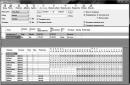
On UAZ-469 instrument panels(Fig. 8) there is a speedometer 17, which shows the speed of the car in km/h, and a counter installed in it shows the total mileage of the car in km. The speedometer scale has a hole for the indicator lamp (with a blue lens) for the high beam headlights. Ammeter 2, used to determine the strength of the charging (the arrow deviates to the right, towards the “+” sign) or discharge (the arrow deviates to the left, towards the “-“ sign) current of the battery.
Turning headlight switch 3 is installed on UAZ-469 and UAZ-469BG vehicles, and when there is no switch, a plug is inserted into the hole. Oil pressure indicator 4 shows the pressure in the engine lubrication system in kgf/cm2. Indicator lamp 5 for emergency oil pressure drop with a red lens. The warning light comes on when the ignition is turned on and goes out after the engine starts running. A short flashing of the lamp when the engine speed decreases does not indicate a malfunction of the lubrication system, if the lamp immediately goes out when the engine speed increases. The indicator lamp 6 of the turn indicators with a green lens lights up when the turn indicators are turned on.
Rice. 8. UAZ-469 - instrument panel.
Coolant temperature indicator 7 shows the temperature of the liquid in the cylinder block when the ignition is on. The sensor for this indicator is located in the water pump bracket. On the UAZ-469 instrument panel, warning lamp 8 for emergency coolant overheating with a red lens lights up when the liquid temperature is above 106...109°C. The sensor is located in the upper radiator tank. The 9th fuel level indicator has a scale with 0 divisions; 0.5; P, corresponding to the empty, half and full capacity of the tank. The fuel level indicator is equipped with two sensors, according to the number of tanks, and shows the amount of fuel in each tank separately. To turn on the right or left tank sensor, there is a switch 12 on the instrument panel, which has two positions: down - the right tank sensor turns on; up - left tank sensor. The indicator is only valid when the ignition is on. Switch 10 of the body light. Handle 11 is used to manually control the carburetor throttle; When the handle is pulled out, the damper opens. The position of the handle can be fixed by rotating it 90° around its axis. The handle must be recessed while the vehicle is moving. The combined ignition and starter switch 13 (lock) (Fig. 9) has three positions: middle - off, first right - ignition on;
second (far right) - ignition and starter are on; third left - the receiver is turned on (when it is installed). Handle 14 (Fig. 8) of the central light switch is used to turn on the headlights, headlights, rear lights and instrument lighting lamps. The switch handle has three fixed positions: the first - everything is off; second - the front lights are turned on (or low beam headlights depending on the position of the foot light switch), rear lights and instrument lighting; third - the low or high beam headlights are turned on depending on the position of the foot light switch, the rear lights and instrument lighting are turned on. By turning the switch knob, the intensity of the instrument lighting is adjusted.

Rice. 9. Key position in the ignition switch of UAZ-469:
O - neutral position; I - ignition is on; II - ignition and starter are turned on; III - the receiver is turned on (if installed).
Switch 15 of the body heater electric motor can be set to three positions: by moving the switch handle up, an increased speed of rotation of the electric motor shaft is turned on, by moving the handle down, a reduced speed of rotation of the electric motor shaft is turned on, and with the handle in the middle position, the electric motor is turned off.
On UAZ-469 instrument panels handle 16 is used to manually control the carburetor air damper; by pulling the handle, you can partially or completely close the air damper - the working mixture is enriched. After the engine warms up, the handle should be recessed. The position of the handle can be fixed by rotating it around its axis by 90°. Switch 1 is designed to control the operation of the windshield wiper and washer; turning clockwise turns on the wiper, and pressing the handle in the axial direction turns on the washer. Button 18 thermal fuse in the lighting circuit. 19 - alarm switch. To turn on, pull the handle towards you.
All control devices of the UAZ Patriot car are combined into one instrument cluster or, in other words, an instrument panel. Depending on the configuration and engine class, the UAZ Patriot is equipped with various modifications of the instrument cluster 59.3801 produced by the Avtopribor plant.
Dashboard of UAZ Patriot.
All electrical connections of the instrument cluster are printed circuit board mounted on the rear side of the instrument cluster. The speedometer is controlled using a speed sensor installed on the transfer case on the speedometer gear fitting. The remaining control devices are controlled from the corresponding sensors on the engine. The tachometer is controlled from the engine control.
The instrument panel is not repairable and if the control devices fail, it must be replaced as an assembly. To replace the backlight lamps or turn signal indicator lamps, the instrument cluster must be removed from the vehicle. The method for checking the serviceability of the control devices of the panel is in, and the procedure for checking the sensors of the control devices is in.
Connecting dimensions, connection diagrams and reference indicators of control devices on the UAZ Patriot instrument panel.
Instrument panel 591.3801010, wiring diagrams, connectors, connections, instrument benchmarks.
Instrument panel 591.3801010-12 for UAZ Patriot with ZMZ-51432 CRS engine, diagrams, connectors, connections, instrument benchmarks.
Instrument panel 596.3801010-10, wiring diagrams, connectors, connections, instrument benchmarks.
Modifications of the instrument panel 59.3801 for the UAZ Patriot.
— Instrument cluster 591.3801010 for cars with a Euro-2 engine: two liquid crystal indicators, four dial gauges, a total and daily mileage counter, an indication of time, oil pressure, on-board voltage, ABS and EBD alarms. Catalog number 3163-3801010-20.
— Instrument cluster 591.3801010-10 for cars with a Euro-2 engine: everything is the same as 591.3801010, additionally equipped with EDC - fuel injection system and COC - catalytic indicators. Catalog number 3163-3801010-20.
— Instrument cluster 593.3801010 for cars with an Iveco diesel engine: everything is the same as 591.3801010, some of the signals are transmitted via the CAN bus. Catalog number 3163-3801010.
— Instrument cluster 593.3801010-10 for cars with an Iveco diesel engine: everything is the same as 593.3801010, plus additional EDC and COC indicators. Catalog number 3163-3801010.
— Instrument cluster 594.3801010 for cars with Euro-2 engine: everything is the same as 591.3801010, but without ABS and EBD warning lights. Catalog number 3163-3801010-30.
— Instrument cluster 594.3801010-10 for cars with a Euro-2 engine: everything is the same as 594.3801010, plus additional EDC and COC indicators. Catalog number 3163-3801010-30.
— Instrument cluster 595.3801010 for cars with an Iveco diesel engine: everything is the same as 593.3801010-10, but without ABS and EBD warning lights. Catalog number 3163-3801010-10.
— Instrument cluster 596.3801010 for cars with a Euro-3 engine: everything is the same as 591.3801010, some of the signals are transmitted via the CAN bus. Catalog number 3163-3801010-40.
— Instrument cluster 596.3801010-10 for cars with a Euro-3 engine: everything is the same as 596.3801010, plus additional EDC and COC indicators. Catalog number 3163-3801010-40.
— Instrument cluster 597.3801010 for cars with a Euro-3 engine: everything is the same as 596.3801010, without ABS and EBD warning lights. Catalog number 3163-3801010-50.
— Instrument cluster 597.3801010-10 for cars with a Euro-3 engine: everything is the same as 597.3801010, plus additional EDC and COC indicators. Catalog number 3163-3801010-50.
Removing the standard UAZ-Hunter instrument panel.
First of all, you need to disassemble the standard panel of the car.
Namely: remove the speedometer (it is electronic, so there will be no hassle with pulling the cable), the rheostat for adjusting the brightness of the instrument lighting (located next to the speedometer), the instrument panel (fuel, pressure, temperature, voltage), the cigarette lighter, the red emergency button , choke handle (it must be removed completely along with the cable - to do this, unscrew 2 bolts on the carburetor and one nut on the panel), headlight hydraulic corrector (not the whole one, but only the one located in the cabin - it is to the left of the steering wheel, secured with one nut), navigation handle (attached with 2 bolts - unscrew carefully - you can cut yourself on the protruding sharp parts of the “iron panel”!), you can immediately remove the panel with switches and switches (headlights, heater, fog lights, interior lighting, switching between tank sensors).
 Then a big question arises - do we need the old panel in perfect condition? What does it mean?
Let me explain: you can remove it,
1) cutting out a small part below the steering column or
2) dismantling the steering wheel, steering column switches and ignition switch. Have you decided? Then let's move on:
I first tried to remove the steering wheel: I removed the top trim, unscrewed the nut (secures the steering wheel to the shaft), drilled holes in the puller (crankshaft pulley from Volga) to the required diameter (everything is checked locally), screwed this puller to the steering wheel hub (even the thread threaded in the hub), but it was not possible to lock the bolts with nuts (the slip ring with the reverse side"steering wheels"), began to slowly pull the steering wheel off the shaft: As a result, after 10 minutes of struggle, the thread in the hub gave up! The steering wheel remained in place! But they say that they don’t screw it on at the factory! After the second attempt (which failed), it was decided not to remove the steering wheel (True, the barbaric path remained - quote: “: use a sledgehammer!”, but he refused it - it’s a pity for the bearings).  The standard panel was mercilessly cut.
The last stage of dismantling was unscrewing the 8 bolts of 2 “frame lock brackets” or, more simply put, the linings securing the windshield frame.
Installing the middle part of the Victoria instrument panel.
First of all, it is necessary to disassemble the Victoria panel (hereinafter referred to as Victoria) into parts.
Next, by fitting the middle part to the “iron panel” (the plastic should fit closely to the iron, at least from the bottom and along the edges), holes for the bolts are outlined (they are also the bolts of the “frame lock brackets” (see above). I attached the panel with 4 bolts .
It’s better to mark with two people - one holds it, and the other, bending over with the letter “Zyu”, marks the holes. We drill holes. We fasten the panel (temporarily), mark at least one more hole - where the instrument cluster was previously attached, there are still threaded holes - use them! In general, the problem of fitting plastic to iron is now being solved. Secured? - Let's film!
 The next stage: we carefully examine the headlight hydrocorrector - along the trim (0 is located on the right), in a special recess to the left of the steering wheel, we mark a hole in the plastic (one must take into account that the hole made to the size of the trim will have to be modified with a file!), and drill it out. We put the plastic in the “piece of hardware” and outline the area where the hydraulic corrector will be located. We cut a hole in the intended area so that the hydraulic corrector housing can easily fit into it (about 6 cm in diameter).
We try it on, and if we successfully complete this stage, we move on to the next one.
Glove box (glove box): We apply (or better yet, secure) plastic - close the glove box and mark where the reciprocal parts of the magnets will be located. I had to make spacers (made of wood) 2.5 - 3 cm thick between the “piece of iron” and the mating part of the magnets (again in place). Here lies another dissatisfaction with the panel - they should make the drawer deeper by these 2 cm: We screw the mating parts of the magnets.
 Now let's decide on the windshield defroster! Will it leave the standard airflow or install a new one? If it's a regular one, there are fewer problems. I chose the second path (Red Pill Matrix).
The second way involves installing side window deflectors from the pre-restyling Gazelle (the left and right deflectors are different!) in specially designated places on the top of the Victoria panel. We dismantle the standard windshield defogger system (4 bolts and a few strong words). Now, applying the upper and lower parts, we roughly mark the location of the hole for the corrugated hose of the right deflector (the main thing is to get between the glove compartment and the center console).
We cut out a hole; for me it turned out to be on top of the hole from the cigarette lighter (I advise you not to save money and make the hole larger than the diameter of the corrugation! - the reason is further.). The left hose will go through the hole from the speedometer.
Now you can finally screw the middle part of Victoria onto the hardware.
We fix the hydraulic corrector in plastic - the hoses may not be long enough! But if you look under the hood in the headlight area, you can see a huge supply of these hoses - let's use it! How? - loosen the attachment points to the body and pull it out of the cabin a little (just not by the body!!). Secured? We fasten the left and right “frame lock brackets” to the windshield frame (bolts for a Phillips screwdriver). On top of them we screw the middle part of Victoria with 4 bolts. We fix it in the center, you will have to drill several holes with a 3 mm drill and secure it with self-tapping screws with large heads (by the way, I still don’t understand why the Kompositovites didn’t use them, standard screws have a rather large (compared to the thickness of the plastic) threadless surface and do not rigidly fix the fastened parts).
We drill a hole for the “choke” handle (air damper control), fasten the handle (we pass the standard cable through the hole, the nut and the stove + engine shield), you can immediately connect it to the “carb” and adjust it.
Screwed on? Is there anything loose anywhere? Let's move on.
Let's now work on the top of the panel and instruments.
First of all, we need to determine which instruments we want to see constantly “in front of us” and place them under the steering wheel (next to the speedometer). I decided it was more important to see the engine oil pressure and engine temperature. It's a shame that there's no room for a tachometer. Although you can always find a place for electronic ones. Have you decided? Then we cut holes in the fiberglass (hole diameter = device diameter) in specially designated areas. We install devices. When I wrote about dismantling the standard panel, I forgot to mention 2 blocks of indicator lamps. We also cut holes for them below the instrument cluster.
 Let's move on to the windshield airflow. The following deflectors are required - 3302-8108095 and 3302-810894 (or from the pre-restyling Gazelle). We place the deflectors in the stampings so that the air flow hits a point on the glass in front of the eyes of the driver and passenger.
With such an arrangement, a problem arises - it is difficult to put the corrugation on the deflector - so we attach the corrugation directly to the deflector and remember about the hole in the “piece of hardware” for the corrugation - you will have to pull the corrugated hose through it! (Later, during the finishing process, I remembered a method applicable to any materials - if you immerse the hose in hot water, it becomes softer and more flexible - fewer problems with installation!)
One more thing: you will have to buy different hoses - the standard ones are 65 cm long - but you need 75 cm! Kompozitovtsy claim that it fits from the TAZ 2106 - no matter how much I tried it (the hose), I still couldn’t understand where it fits: If you try hard, then the UAZ corrugation should be enough for the right deflector, but with the left one you’ll have to be tricky: I extended the hose a piece from the same hose (about 12 cm is needed).
The preparation of the upper part is complete.
Preparing the central part of the panel.
 We install the remaining instruments (fuel level and voltage in the on-board network) - there is only one mounting slot left. There’s a lot of choice here - you can install a “shahi” clock, or an ammeter, etc. (who knows what:).
Below we have control buttons for interior lighting, front and rear foglights, emergency lights, etc. Even lower is a place for a radio or trip computer.
 To install the radio, you need to cut a window in the panel according to the size of the landing basket (or the radio itself).
It is also necessary to enlarge the standard hole in the center of the middle part of the panel (approximately in the area where the standard instrument cluster used to be). Moreover, it is necessary to increase it to the size of the hole for the standard instrument cluster. The mounting lugs with pressed-in nuts should be bent inward. Power can be supplied from the fuse block - there are a lot of free sockets, I put a 10A backup fuse in place, 5A is enough for the radio (without an amplifier).
When installing the radio, there will be problems with the wiring. The tourniquet needs to be lengthened!
Let's continue preparing the central part of the panel:
Even lower are the switches for external lighting modes (headlights, dimensions), operating modes of the stove engine, switch for gas tank sensors, etc. (be careful with installation - the plastic of the clamps is fragile and breaks - I had to glue the switches for lighting modes and stove operation using liquid nails - nothing else would hold).
Cut out a hole for the choke handle with a diameter the size of the choke handle. :. Why so big? In order for the central part of the panel to be relatively easily removable.
Even lower, to the right of the recess under the choke handle, we place a brightness control for the instrument lighting and a cigarette lighter.
We are preparing the electrical wiring.
This step involves extending the wires and adding several plug connections. It is necessary to extend the wires to the instruments located under the steering wheel (for the speedometer it is not necessary - the wires reach). I had to lengthen the wire connected to the lighting lamps (gray), ground wire (black), instrument power wire (red) - by about 30 cm each.
I was lying in the previous paragraph - preparing the wiring actually took about 7 hours (including running around the shops).
1) It is necessary to extend the wires to all devices and switches!
The wires to the devices in the upper and central part of the panel must be assembled into several connecting blocks (hereinafter simply “blocks”). For existing terminals, it is necessary to lengthen the wires - the best solution is to reassemble the group of the required length and secure it to the ends of the terminals.
2) In place of the blocks for the switches ("directional" and with a complex arrangement of contacts), we put ordinary blocks (with a parallel arrangement of contacts). We assemble the blocks for the switches with wires of the required length (about 25 cm) and the second part (“male”) of ordinary blocks.
3) We also extend the wires to the “emergency” button and the resistor-dimmer of the brightness of the instrument lighting, using the technology from step 2.
4) We supply power to the radio (see above) and connect the wires to the speakers, antenna, etc.
If the contact blocks are the same color, then you need to somehow mark those corresponding to one device.
We're done with the preparations. Let's move on to assembly.
Victoria panel assembly.
We assemble, if disassembled, the steering column switches, the ignition switch and their casing. The casing will have to be trimmed a little (in place), just be careful - otherwise there will be a “hole” in the most visible place.
We install the upper part of Victoria, connect the wires to the instruments and indicators. We secure it with standard self-tapping screws and metal brackets; to increase rigidity, I duplicated them, and in some places replaced them with self-tapping screws with a wide flat head. In the center it is necessary to secure the panel not only with a pair of standard screws (they hardly hold)! We drill a couple of holes through the plastic and metal (just in the space between the socket for the indicators and the instrument cluster), fasten it with self-tapping screws.
We don’t touch the sides yet: 
We install the steering column protection shield. To do this, a hole is cut in it for the ignition switch, and a pair of holes for self-tapping screws are drilled through it, the middle part of the panel and the hardware. The third self-tapping screw secures the shield to the standard steering column casing.
We install the central part: we connect the wires to switches and devices, the radio, etc. The path of laying the harnesses depends on how much the wires are extended. My main harness went to the right of the radio. When arranging the wires and connectors, it is necessary to take into account the presence of the cigarette lighter (heating) and windshield wiper rods.
 Pull out the choke handle and pass it through the hole in the panel. The radio basket or the radio itself must fit into the hole in the plastic + piece of hardware. Laying out the wires. We combine the holes on the middle part of the panel and on the central part of the panel. We secure the central part with self-tapping screws - 2 on top, 1 in the recess under the choke handle.

 We secure the left and right pockets (3 screws each).
We install the pistons in the holes (you can widen them a little). We fix the decorative “moldings”.
All? Nothing like that!
 When engaging 1st or 3rd gear on a 4-speed gearbox, I got my fingers pinched between the panel and the gearshift knob!
Let's disassemble the "half-cabin", or rather the floor of the salon.
We remove the “turtle” (you can only use one left half), put the gearbox in neutral, unscrew the 4 bolts securing the handle joint to the gearbox, remove the handle (try not to tear the gasket).
Bend the handle in a vice or other improvised means (just not too much). We assemble everything in reverse order.
Although this “state” of the unit can be used to top up the transmission above the level (I did a similar thing - I added 300 ml of ZIC 80W90 to the gearbox and 2 cm below the upper shaft to the RC, I’ll let you know what happens to the unit later).

Have you assembled it, screwed it on, put in rugs and other bells and whistles? Now that's ALL.