Good day Dear Radio Amateurs!
For almost a month now, the section “ From readers“. To be honest, I was already beginning to think that this idea of mine was a failure - there was no response from readers to the proposal. And this morning, while looking through the site’s mail, I was pleasantly surprised to find a letter inviting me to publish an article. But I was even more surprised, and one might even say amazed, when I saw who the author of the article was.
So, dear Radio Amateurs, today, in the “From Readers” section, it is with great pleasure and respect that I present to you an article by the author of many interesting and informative publications and books - Yuri Vsevolodovich Revich:
Refinement of solar-powered garden lamps
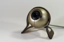
Several years ago, in large supermarkets (Auchane, Leroy-Merlen) surprisingly cheap (priced less than a hundred rubles) garden lamps with LEDs and with built-in solar battery th for recharging during the day. After some time, they appeared in almost all retail outlets selling electrical items or gardening supplies. The lamp looks something like this:
A good initiative, however, turned out to be somewhat spoiled by the fact that the brightness of the small LED is not enough to seriously illuminate something, so the lamp rather performs decorative functions and quickly gets boring with its deathly white glow. In addition, in real light conditions, the power of the solar battery is not enough to recharge the battery normally - the lamp burns for two to three hours after sunset and then “dies”.
There is, however, a simple way to correct both shortcomings at once, and turn the product from a disposable toy into a beautiful and functional element garden landscape. Of course, it is impossible to turn it into a full-fledged lighting device, but it is easy to significantly improve the decorative qualities of the lamp if you replace the LEDs with colored ones. The latter are available in many different colors (not only white-red-yellow-green-blue, but also different shades - for example, green is not only just green, but also yellow-green and bluish-green, and yellow - and thick yellow and lemon). All of them, both regular and high-brightness, of any size and geometry, can work in these lamps without modification (with the exception of special powerful lighting and still blinking LEDs, which themselves constitute a complete circuit). When replacing, just pay attention to the polarity of the LED, and practically nothing else is required. The lamps work quietly even in winter with slight frosts, but in severe cold weather it is better to put them indoors by removing the battery.
However, the second problem may even be aggravated: a small voltage drop across a color LED will make it burn very brightly, but even in the summer only for half an hour or an hour. This is especially problematic in the fall and winter, when daylight hours are shortened and cloudy weather means that the battery charge accumulated during the day only lasts for a couple of minutes.
This drawback is also easy to correct if you connect a resistor with a value of several tens of ohms in series with the LED. Use a sharp cutter to break the track on the board leading from the microcircuit to the LED and install a resistor in its place (the figure below shows a modification of the lamp board from Leroy-Merlin; in other cases the board may look different):
The resistor should be selected in such a way that the current through it is 4-6 mA - this is enough for normal glow brightness, and when the standard Ni-Cd battery is fully charged at 600 mAh light will then work for several days (in practice, full charging, of course, is not achieved).
At the output of the lamp microcircuit, there is a rough current source with an open-circuit voltage of about 2.5 V - that is, approximately equal to twice the battery voltage. When a load is connected, this voltage drops, and the resistor must be selected so that the voltage drop across it corresponds to the selected current. For example, for a red LED the rating can be 75-91 Ohm (voltage drop across the resistor 0.4-0.5 V), for a green high-brightness LED - from 47 to 62 Ohm (voltage drop 0.2-0.3 V) and etc.
By the way, usually a standard Ni-Cd battery lasts no more than a year, then it breaks down. Experience has shown that a regular AA Ni-MH battery can be installed in the lamp, and the cheaper (that is, the lower its capacity), the better - the existing solar battery is still not enough to fully charge a battery with a capacity of 2000-3000 mAh , and in any case it will work only at a small part of its capabilities.
For those who (due to their youth) are unfamiliar with Yu.V. Revici:
 Engineer and journalist with many years of experience. Main range of interests – information Technology, their influence on modern society, technological innovation, history of computers and technological innovation. Regularly published in magazines, newspapers and online publications. Author of 6 popular books, including “Entertaining electronics”, “Self-instruction manual for working on a PC for everyone”, “Practical programming of Atmel AVR microcontrollers in assembly language”, etc.
Sunny Charger at 5 volts/power supply.
In that textbook I used 5 solar lights.

I selected a container that was within the experimenter's budget and also one that had some of the qualities I was looking for.
This box has 4-way binding function. It's easy to open/easy to close, etc. One thing I liked was the rubber gasket built into the lid part.
This should make the container fairly waterproof.
I can use this during emergencies. Solar charger for mobile phone or another gadget would be convenient.
Step 2: Preparing the Cell and Battery Combination


The underside/base has three screws that need to be removed. I cut the RED and BLACK wires (positive and negative) on both the battery and solar cell where they are connected to the board.
After the light assembly was removed, I turned the cell upside down. I used a sharp paring knife to strip about 1/3-1/2 inch of wire.
Next you need to connect both red wires together, as well as the two black wires. This creates a parallel circuit between the solar cell and the nickel-cadmium battery.
I created an extra red wire that I used to connect cell to cell.
Step 3: Assembly


In this picture you can see 5 cells connected positively and negatively in a series circuit.
Each battery is known as a 2/3 AA cell. They are 1.2 volts when charging. We should get a voltage of approximately 6 volts or more. As you can see I had 6.25 volts with no circuit loaded.
This voltage will give us enough voltage to regulate it to somewhere between 4.8 and 5.2 volts. Most 5-volt devices charge between 5 and 5.2 volts.
As some of you know, a zener diode can reduce the voltage of a circuit by 0.5-1 volt if placed in a circuit.
The second picture shows the zener diodes I used. They show a voltage drop of about 1/2 volt each.
Using a voltage regulator such as the LM317 would be counterproductive as the losses would be too high.
I put 2 diodes in series and got about a 1 volt drop, exactly what I was looking for.
As you can see the meter shows 5.11 volts with no load, this should work very well.
I'm guessing it will take a while to charge the phone due to the low amperage.
Step 4: Assembly


Here you can see all 5 cells in the container sitting loosely.
I decided to use the female end of the USB cable to connect.
The second picture shows the connection USB cable. Red and black are obviously positive and negative. Green and white wires are not used. The green and white wires are for data transmission in a computer context.
I poked a hole at the end of the container. After tying and feeding the USB line through the side, I tied another knot to secure it somewhat.
Using a female USB cable, you can disconnect all other 5V auxiliary cords for different devices.
I will likely use clear silicone around the cable gland to keep it moisture resistant in bad climates.
Step 5: Protecting Components

I believe a picture is definitely worth a thousand words.
All I can say is that hot glue is my friend.
You'll notice that I also attached two zener diodes to the side of the center cell housing. I also used about one drop of glue on the solder joint after carefully trimming the excess wire.
Hot glue really helps secure the connections on these very thin wires.
Step 6: Results of making a charger from solar garden lights

 Basically I got 5.09 volts DC.
You will see a micro-USB charging cable from my cell phone.
******* JUST A NOTE *******
You may remember that to work with hot glue, you need a damp (wetter than dry) sponge.
First, hot glue is dangerous if handled carelessly.
Children should not use hot glue without help!!!
**When I attach the camera to the container, I suggest keeping it simple.
Be careful with hot glue on solar cells. I doubt the glue will harm them, but it will look messy.
After spraying glue around the cell, keep your finger on the cell/battery body to hold it in place. then lift the container and place it on a damp sponge to absorb excess heat from the adhesive joint.
This keeps things cool safely and allows you to move forward faster when components accidentally become dislodged.
I hope you got some creative ideas for your next project.
Enjoy!
Many summer residents dream of decorating their garden plot at night with portable solar-powered flashlights, but many simply cannot afford such luxury. There is a way out: by assembling lamps with your own hands from inexpensive radio components, you can easily organize a real scattering of lights in the garden.
Purchased lamps more often disappoint than delight. They shine dimly, work only for a few hours and hardly last longer than two years. When assembling a garden lamp with your own hands, you determine the necessary parameters yourself and can count on a guaranteed result.
The operating principle of such a lamp is very simple. During the daytime, the sun hits a photocell, which generates electricity and charges a small battery. When the solar panel voltage drops, a transistor switch cuts off the current from the solar panel to the battery and supplies power to one or more bright LEDs. When voltage appears at the photocell contacts, reverse switching occurs.
What parts are best to order and where?
The most difficult thing is to get hold of solar cells. Substandard items are suitable; the easiest way to buy them is on various online auctions, such as Aliexpress. Select a module with an output voltage of at least 5 volts; the power must correspond to the number of LEDs. It is very important that the module has conductor taps; otherwise, buy those that come complete with flat conductors and a flux pencil.

The most expensive element of the lamp is the nickel-metal hydride or lithium-ion battery. Requires 3.6V batteries, they look like three AA batteries, covered in film. The capacity must also correspond to the total power of the LEDs multiplied by the number of hours battery life+ 30%. Can be purchased together with modules.

Light sources are LEDs. Based only on the characteristics, you most likely will not be able to choose the appropriate level of illumination, so you will have to choose experimentally. It is recommended to use bright white LEDs BL-L513. They are easy to find in electronic components stores, for example, at Chip and Dip they cost 10 rubles. Each LED requires a 33 ohm current limiting resistor.

Also, for each lamp you need a 2N4403 transistor, a 1N5391 or KD103A rectifier diode, as well as a resistor, the value of which is calculated using the formula R = U baht x 100/N x 0.02, Where N- the number of LEDs in the circuit, and U baht— battery operating voltage.

How much will the parts cost?
In cheap Chinese lamps costing about 500 rubles. Only one LED is used, which is clearly not enough. Moreover, the battery voltage is 1.5V, which is why the light is very dim.
| Elements | Price | Qty | total cost |
| Solar modules Eco-Source 52x19 mm | 675 rub. for 40 pcs. (for 4 lamps) | 1 set | RUB 675.00 |
| Battery SONY HR03 (1.2 V 4300 mAh) | 885 rub. for 12 pcs. (for 4 lamps) | 1 set | RUR 885.00 |
| LEDs BL-L513UWC | 10 rub./pcs. | 12 pcs. | RUB 120.00 |
| Resistor CF-100 (1 W 33 Ohm) | 1.8 rub./pcs. | 12 pcs. | 21.60 rub. |
| Transistor 2N4403 | 6 RUR/pcs. | 4 things. | RUB 24.00 |
| Diode 1N5391 | 2.5 RUR/pcs. | 4 things. | 10.00 rub. |
| Resistor CF-100 (1 W 3.6 kOhm) | 1.9 RUR/pcs. | 4 things. | 7.60 rub. |
| Total: | RUB 1,743.20 |
It turns out that to assemble one high-quality lamp you need approximately 435 rubles worth of components. But from these same parts, by purchasing the last 3 items, you can make 12 analogues of cheap Chinese lamps.
Soldering a simple circuit and assembling the parts
To assemble such a circuit, it is not necessary to have a textolite base and etch out the tracks. The cathodes (short leg) of all LEDs are assembled into one unit, and 33 Ohm resistors are soldered to the anodes (long leg). The tails of the resistors are also soldered together and soldered to the collector of the transistor. A 3.6 kOhm resistor is connected to the base of the transistor, and the cathode of the rectifying diode is connected to the emitter. The anode of the diode is connected to the base resistor, and the positive pole of the solar modules is supplied to the same unit. The negative from the modules and the battery is connected by wires to the combined cathodes of the LEDs. The positive terminal of the battery is connected to the emitter of the transistor.
 Electrical diagram of the lamp
Individual solar modules have a voltage of 0.5 V, and to charge batteries you need 4.5-5 V. Therefore, individual modules must be combined into chains. First, solder the conductors to the modules if there are none. To do this, cut the flat conductor into strips slightly longer than the width of the module. If the module is 19 mm, cut 25 mm.
The positive contact of the module is located on the back side, and the negative contact is that same central strip on the front part. You need to run flux along this strip - this is a colorless marker from the kit. Then a piece of conductor is laid over the contact. All that remains is to slowly move the soldering iron from above: a thin layer of tin is already on the conductor. The remaining tail is soldered to the contact on the back of the next module and so on along the chain until 10 modules are assembled in two rows.

Between the rows you need to make a jumper from a flat conductor, and solder thin copper wires to the remaining two ends. Be careful when handling the modules, they are very fragile. It is also not advisable to overheat them, so do not keep the soldering iron in one place for too long.
Design and assembly of the lamp
The lamp requires a housing, preferably waterproof. It is very convenient to use an empty canning jar with a screw-on lid.
 Example of parts layout
To assemble such a lamp, you need a piece of plywood to glue two rows of modules onto it. The proposed photocells have a size of 52x19 mm; folding them in two rows will result in a rectangle with dimensions of approximately 110x110. You can glue the modules using double-sided tape for mirrors, but do not press down too hard.
Before gluing the modules, cut a hole in the center of the board for the lid of the jar and secure it inside with a couple of drops of hot glue. You need to pierce two holes in the cover to enter wiring from the modules; do not forget to restore the seal later.
To conveniently place electronics inside, glue a small foam washer to the inside of the lid. If you don’t bite the legs when soldering the circuit, you can stick the elements into the foam and fix them that way. And if you make rectangular cuts in the foam, you can easily insert batteries into them. For contact, use a pair of flattened balls of aluminum foil with wires soldered to them.

Before closing the lid, warm the inside of the jar well with a hairdryer. This way the parts will oxidize less, and condensation will not appear on the walls of the jar.
Some operating secrets
Lamps do not tolerate cold very well, so it is advisable to bring them into a warm room for the winter. The batteries need to be completely discharged by covering the solar panel with something opaque. Wrap the batteries separately in paper to help them last longer. Also consider covering the modules with a clear protective coating or using film solar cells. In general, such lamps last for 6-7 years of active use.
If you are thinking about organizing lighting for your garden plot, then do not rush to buy lighting in the shop. You can make solar-powered garden lamps with your own hands.
If you want to illuminate an open area, but it is difficult to supply electricity to it, then you should think about solar-powered lamps, the batteries of which are charged by the rays of the sun. With the onset of darkness, such devices begin to work, creating a comfortable environment in your garden. The lamps are easy to use and install, and are also quite attractive. affordable prices on them and a wide selection.
Solar garden lamp
This article will be of interest to those who like to create useful things around the house with their own hands. One of the advantages of making lamps “on your own” is that your model will be exclusive and completely reliable (after all, you made it yourself). Remember: realize significant savings Money It's unlikely to succeed. We will not describe expensive circuits using ready-made controllers, but will focus only on the simplest option. Almost anyone who has ever held a soldering iron in their hands can repeat it.
Schematic diagram of an easy-to-replicate lamp
Below circuit diagram a lamp powered by sunlight is very simple, and has been tested many times by numerous amateurs who specialize in making useful devices with their own hands.

Schematic diagram
How it works:
- During the daytime, the solar panel (S) converts the energy of light rays into electricity.
- The current it produces through diode D1 charges battery(A).
- The positive potential applied to the base through resistor R1 “holds” transistor T1 in the off state and LED D2 does not light up.
- When the solar panel illumination decreases significantly, the transistor opens (due to a decrease in the positive potential applied to the base) and connects LED D2 to the battery. The LED starts to light up.
- Diode D1 prevents the battery from discharging through the solar panel.
- With the onset of dawn, the positive voltage coming from the “+” output of the solar panel to the base “closes” transistor T1 and LED D2 stops lighting, and the battery begins to charge again.
Criteria for selecting parts and prices
The choice of parts depends on how powerful the lamp you intend to make. We provide specific ratings for a homemade lighting device with a power of 1 W and a luminous flux intensity of 110 Lm.
Since in the above diagram there are no elements for monitoring the battery charge level, then, first of all, you need to pay attention to the choice of solar battery. If you choose a panel with too little current, then during daylight hours it simply will not have time to charge the battery to the required capacity. Conversely, a light panel that is too powerful can overcharge the battery during daylight hours and render it unusable.
Conclusion: the current generated by the panel and the battery capacity must match each other. For a rough calculation, you can use the ratio 1:10. In our specific product, we use a solar panel with a voltage of 5 V and a generated current of 150 mA (120-150 rubles) and a battery form factor 18650 (voltage 3.7 V; capacity 1500 mAh; cost 100-120 rubles).

Also for production we will need:
- Schottky diode 1N5818 with a maximum permissible forward current of 1 A - 6-7 rubles. The choice of this particular type of rectifier part is due to the low voltage drop across it (about 0.5 V). This will allow you to use the solar panel most efficiently.
- Transistor 2N2907 with a maximum collector-emitter current of up to 600 mA - 4-5 rubles.
- Powerful white LED TDS-P001L4U15 (luminous flux intensity - 110 lm; power - 1 W; operating voltage - 3.7 V; current consumption - 350 mA) - 70-75 rubles.
Important! The operating current of LED D2 (or the total total current when using multiple emitters) must be less than the maximum allowable collector-emitter current of transistor T1. This condition is met with a margin for the parts used in the circuit: I(D2) = 350 mA< Iкэ(Т1)=600 мА. Battery compartment KLS5-18650-L (FC1-5216) – 45-50 rubles. If, when installing the device, you carefully solder the wires to the battery terminals, you can refuse to purchase this structural element.
- Resistor R1 with a nominal value of 39-51 kOhm - 2-3 rubles.
- We calculate the additional resistor R2 in accordance with the characteristics of the LED used.
Purpose and calculation of an additional resistor in the LED power circuit
The battery voltage may be too high for the LED (this may cause it to fail). To compensate for its excess we use an additional resistor R2. We calculate its denomination based on the formula: U(A) = U(D2) + U(R2), where:
U(A) – battery voltage;
U(D2) – LED operating voltage;
U(R2) – voltage drop across additional resistor R2.
For the TDS-P001L4U15 LED used in the above circuit with an operating voltage of 3.7 V, the use of resistor R2 is not required, since U(A) = U(D2). That is, our specific scheme will look like this:

As an example of calculating additional resistors, consider a circuit with the connection of two different types of LEDs: D2 - BL-L813UWC (operating voltage - 2.7 V; current consumption - 30 mA; cost - 15 rubles) and D3 - FYL-5013UWC/P (2, 2 V; 25 mA; 20 rubles).

We calculate the additional resistor R2 for LED D2.
U(A) = U(D2) + U(R2)
U(R2) = U(A) – U(D2) = 3.7 – 2.7 = 1 V
According to Ohm's law (familiar to everyone from school):
U(R2) = R2 I, where I is the current consumed by the LED, therefore
R2 = U(R2) : I = 1: 0.03 = 33.33 ≈ 33 Ohm
Similarly, we calculate the additional resistor R3 for LED D3:
U(R3) = U(A) – U(D3) = 3.7 – 2.2 = 1.5 V
R3 = U(R3) : I = 1.5: 0.025 = 60 ≈ 62 Ohm
On a note! After calculations have been made, the values of additional resistors are rounded to the nearest standard values.
The final circuit with two different types of emitters will look like this:

Installation
The circuit consists of a minimum number of elements, so installation can be easily carried out using a hinged method. The length of the “legs” of the parts will be quite enough to perform soldering without the use of additional wires. After completing installation and checking the functionality of the manufactured luminaire, all joints should be insulated using a heat pencil or appropriate sealant.
For those who prefer to mount components on printed circuit board, can do this by using a universal circuit board of suitable dimensions or making one yourself.
What is the lampshade made from?
Before we tell you what shapes can be used to make a lampshade, let us remind you of the requirements that must be observed when self-production lamp body:
The solar panel should be located outside on the top of the product so that it is well illuminated during the daytime.
All connecting seams between structural elements must be carefully sealed (the components of the circuit are afraid of moisture).
LEDs must be placed in the transparent part of the lampshade.
Otherwise, everything will depend only on your imagination, personal preferences and available materials. One of the most simple options is the use of a glass jar as a lampshade (for example, for storing bulk products) with a wide neck and a tight lid:
- make a hole in the lid and pass the wires from the solar panel through it;
- fix the solar panel on the outside using sealant;
- We mount the battery compartment and circuit elements on the inner surface;
- We place the LEDs at the bottom of the can.

You can successfully use a food container made of transparent plastic as an almost finished case. There are a large number of such products on sale in various sizes and shapes (round, square, rectangular). The choice will depend on the size of the solar panel and the number of LEDs.

In custody
Repeating the simplest scheme and having acquired the necessary manufacturing experience, you will be able to produce the required number of a wide variety of homemade solar-powered lamps. Such economical and mobile lighting devices will not only decorate your garden plot, but will also significantly increase the comfort of its use in the dark (for example, if you place them along garden paths, above the front door or near a summer gazebo).
If you have any questions on this topic, ask them to the experts and readers of our project.
Many people have probably thought about how to illuminate the local area so that it is both cozy and aesthetically pleasing. But this means additional energy costs. And besides, in order to supply voltage to each of the street lamps, you will have to ruin the landscape and dig ditches into which the cable will be laid. Well, wires hanging in the air from one garden lamp to another is completely unsightly.
And here the thought arises: “But you can install a lantern on a solar battery, and then electrical energy will be produced this way.” free generator, like a sun!". Naturally, a person goes to the store to buy such devices and, looking at the prices of these lighting devices, forgets about his desire, because their cost is very high.
But there are hands and a head, and this device was created by the same people, which means that it is quite possible to assemble a solar-powered garden lantern with your own hands.
Let's try to figure out whether this is possible and how difficult this work is.
Preparatory work
Of course, the ideal option would be if you have a faulty device - in addition to understanding its structure, you can at the same time understand how to repair a solar lantern with your own hands, but there is also a drawback in the implementation of this idea. Naturally, you can take several cheap garden lanterns that require repairs and replace them with solar panels, but upgrading their Chinese filling will still be necessary. Therefore, their base is needed only for training, since a repaired flashlight will not last longer than one made from scratch.
Before you start creating a solar-powered lamp, you need to understand the design of such devices.
Although all flashlights look different, their operation scheme is very simple. It consists of a solar battery (panel), a battery, a voltage converter and an LED or module.
The diagram of such a lamp will be clear to any novice radio amateur and it looks like this:

And now, having already understood the circuit and understanding the principle of operation of a flashlight that runs on the energy generated by solar cells, you can decide what brightness is required, which light elements to choose, and in accordance with this, choose a battery and solar panel.
Ultra-bright Cree LEDs, 1–1.5 volts, 3 or 4 pieces per lamp, are quite suitable for lighting a summer cottage. With such elements, a battery with a capacity of 3,000 mAh and an output voltage of 3.6 volts will be sufficient. Such a battery will be charged from the solar panel for 8–10 hours, which is quite enough to operate the selected LEDs for up to 12 hours.
And, of course, the solar panel itself. The fact is that the solar battery of garden lamps produced nowadays is very small. A suitable battery would be 65 x 65 x 3 mm in size, with an output voltage of 4.4 V, 90 mA. It may well provide the necessary nutrition.
Electronic control unit. Now you need to assemble the “head” of the lamp, namely the control unit itself. For this you will need:
- four MLT 22 kOhm resistors;
- two KT503 transistors;
- one diode (Schottky 11DQ04 would be optimal).
Since all this will be placed on one board, it is of course better to etch it yourself. But there is an option that is more accurate and less labor-intensive. Nowadays you can buy universal breadboards in stores. In addition, stranded copper wire should be on hand when working to create tracks.
So, when all the elements of the future electronic control unit are assembled, you can start soldering. You need to assemble the following diagram.

4 LEDs are freely included in such a circuit. And if the build quality is at a high level, then such a control unit will last for many years.
Lantern assembly
Naturally, everyone comes up with the shape of a solar-powered lamp themselves; here there is complete scope for the master’s thoughts and imagination. Once the circuit of the electronic control unit is assembled, connecting LEDs to it will not be a problem. Of course, you can turn on a regular switch in the LED power supply, but it will be much more convenient if instead you install a photocell in parallel with the motion sensor. Then, at dusk, the solar-powered lamp, made by yourself, will automatically turn on, and turn off at dawn. Or it will trigger on a passing person, which is also convenient.
It is also possible to connect a controller when using RGB LEDs, then the solar lights will also be adjusted by the color of the glow, and remotely, but in this case you need to understand that it will also need power. Although we are also solving this issue. After all, the choice of solar panels on the shelves of electrical stores these days is unusually wide. This means that choosing the right ones will not be difficult.
 Additional features using solar panels at home
 conclusions
Of course, everyone decides for themselves, depending on their employment and financial situation, what to do - buy such a lamp or make it with their own hands. But it’s not even about the amount spent on new flashlights, although here the savings come out to be more than 4 times.
Isn’t it nice to know that there is a lamp working on the site of a house or apartment that was created not in a factory, but with your own hands, as they say, “on the knee”? This is probably the main reason why you should try to assemble a solar-powered garden lamp yourself.